
Exhaust disinfection device for contaminated waste gas treatment of medical center suction system

A disinfection device and exhaust gas treatment technology, applied in the direction of gas treatment, dispersed particle separation, membrane technology, etc., can solve the problems of difficult to guarantee reliability, difficult to eliminate, high one-time killing efficiency, etc., and achieve scientific and convenient design of technical solutions Maintain and reduce the effect of spreading the virus

Pending Publication Date: 2020-05-08
上海穗杉实业股份有限公司 +1
View PDF0 Cites 0 Cited by
  • Summary
  • Abstract
  • Description
  • Claims
  • Application Information

AI Technical Summary

Problems solved by technology

[0003] After investigation, the following problems exist in the discharge of toxic waste gas from the central suction system of existing hospitals, especially hospitals for infectious diseases: (1) The central suction station is set in the basement, and the exhaust outlet is also set in the basement or in the suction station, and the poisonous waste gas Directly pollute the environment of the station; (2) The medical compressed air station of some hospitals is close to the central suction station, and the medical compressed air inlet is set indoors, and the toxic waste gas may be inhaled into the medical compressed air; (3) Exhaust When the outlet is set outdoors, the distance between the doors and windows of adjacent buildings is less than 3 meters. Affected by the monsoon, the poisoned exhaust gas is easily scattered to the adjacent work area or living area; (4) Most vacuum suction pump stations are not installed For the effective disinfection device for poisonous waste gas, even if some bacteria filtering devices are installed, the filter element will not be replaced for a long time, and the pressure loss will be large, which will directly affect the operation of the vacuum pump. At the same time, the replacement of the filter element will also bring a large maintenance cost to the hospital.
Moreover, as time goes by, more and more impurities are accumulated, and the pressure difference increases, which will seriously affect the operation of the vacuum pump unit and the maintenance of vacuum degree.
If the filter element is replaced, there will be potential safety hazards such as viruses and bacteria, and the replacement of the filter element will also bring high maintenance costs to the hospital.
[0006] There are also other killing technologies such as ozone, high-voltage static electricity, ultraviolet light, and plasma. Since many vacuum pump units in the suction system of medical centers use water ring pumps, the exhaust gas is entrained with a large amount of water. Although it is condensed, it is difficult to get rid of it. Due to the change of dew point temperature during pipeline transportation, the exhaust gas not only contains high moisture content, but also contains a large amount of condensed water. Using these technologies, it is difficult to guarantee the reliability of long-term operation; in addition, chemicals such as chlorination Methods, ozone, high voltage electrostatic, ultraviolet, plasma and other killing technologies need to add harmful chemical substances, and may also produce ozone or other regeneration by-products and hazardous waste; especially, such as ozone, high voltage electrostatic, ultraviolet, plasma, etc. It is difficult for killing technology to achieve a high killing efficiency at one time, and the exhaust gas discharged from the vacuum pump unit of the suction system of the medical center is an organized waste gas discharge, which requires a device with high killing efficiency at one time and can be inactivated immediately. Killing means safe discharge. Otherwise, the total killing efficiency of the device on the discharged toxic waste gas will be ensured through cyclic killing, but obviously this will bring extremely high challenges to on-site engineering practice, and the cost will also increase significantly

Method used


Image

  • Exhaust disinfection device for contaminated waste gas treatment of medical center suction system
  • Exhaust disinfection device for contaminated waste gas treatment of medical center suction system
  • Exhaust disinfection device for contaminated waste gas treatment of medical center suction system

Examples


Embodiment Construction

[0038] In the description of the present invention, the terms "central", "longitudinal", "transverse", "upper", "lower", "front", "rear", "left", "right", "vertical", " The orientations or positional relationships indicated by "horizontal", "top", "bottom", "inner", "outer", etc. are based on the orientations or positional relationships shown in the drawings, and are only for the convenience of describing the present invention and simplifying the description, rather than Nothing indicating or implying that a referenced device or element must have a particular orientation, be constructed, and operate in a particular orientation should therefore not be construed as limiting the invention. In addition, the terms "first", "second", etc. are used for descriptive purposes only, and should not be interpreted as indicating or implying relative importance or implicitly specifying the quantity of the indicated technical features. Thus, a feature defined as "first", "second", etc. may ex...


PUM


Abstract

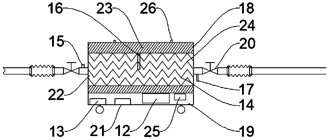
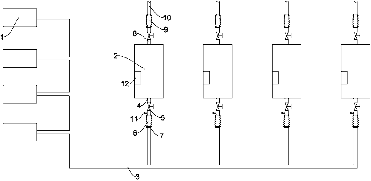
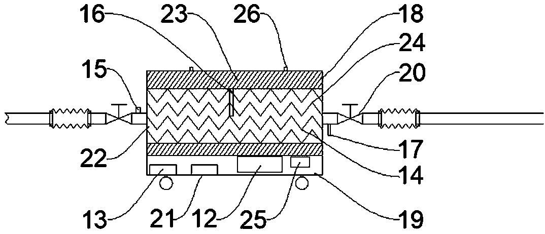
The invention belongs to the technical field of medical equipment, and particularly relates to an exhaust disinfection device for contaminated waste gas treatment of a medical center suction system. The device comprises a power supply module, a thermal killing module, a control system, an incoming flow pressure detection sensor, a temperature sensor, an exhaust valve, a movable chassis, a box body, an interface, a flexible connecting pipeline and the like, wherein the thermal killing module provides electric-thermal conversion for the device, and the module mainly meets the requirement of instant killing temperature; specifically, resistive electric heating elements or microwave, inductive and other electric heating elements are adopted. A wind tunnel structure is preferably adopted, a heat source is formed through direct heating, and higher heat efficiency is achieved; the control system is used for controlling the device to be started and stopped, adjusting the load, monitoring the temperature, adjusting the temperature and giving a fault alarm. A plurality of devices can be connected into a waste gas exhaust main pipe of the medical center suction system in parallel, so that microorganisms such as viruses and bacteria can be immediately and efficiently killed.

Description

technical field [0001] The invention belongs to the technical field of medical equipment, and in particular relates to an exhaust disinfection device for treatment of poisoned waste gas in a suction system of a medical center. Background technique [0002] The vacuum pump unit of the central suction station is used as the negative pressure source in the medical central suction system. Through the suction of the vacuum pump, the front-end piping system and vacuum accessories of the medical central suction system can reach the required negative pressure value, so that it can be used in the operating room, emergency room, treatment room, etc. Vacuum suction is generated at the terminal of the room and each ward. [0003] After investigation, the following problems exist in the discharge of toxic waste gas from the central suction system of existing hospitals, especially hospitals for infectious diseases: (1) The central suction station is set in the basement, and the exhaust ou...

Claims


Application Information

Patent Timeline
IPC IPC(8): B01D53/00
CPCB01D53/005B01D2257/91
Inventor 陈宗蓬陈尊淼吴仁杰
Owner 上海穗杉实业股份有限公司
Learn More