
C-type filter and switch control method thereof

A switching control and filter technology, applied in harmonic reduction devices and AC networks to reduce harmonics/ripples, etc., can solve problems such as affecting equipment life, increasing active power loss of filters, and increasing operating costs of substations. Heating time, reducing active power loss, and realizing the effect of economical operation

Active Publication Date: 2020-05-08
SICHUAN UNIV +1
View PDF6 Cites 5 Cited by
  • Summary
  • Abstract
  • Description
  • Claims
  • Application Information

AI Technical Summary

Problems solved by technology

However, the existing C-type filter can ensure that there is no resonance at the parallel connection of the filter. However, compared with the single-tuned filter, the addition of the R branch will greatly increase the active power loss of the filter, which will cause the equipment to heat up and affect the life of the equipment. The operating cost of the substation is increased, so the C-type filter needs to be optimized according to the system conditions

Method used


Image

  • C-type filter and switch control method thereof
  • C-type filter and switch control method thereof
  • C-type filter and switch control method thereof

Examples


Embodiment 1

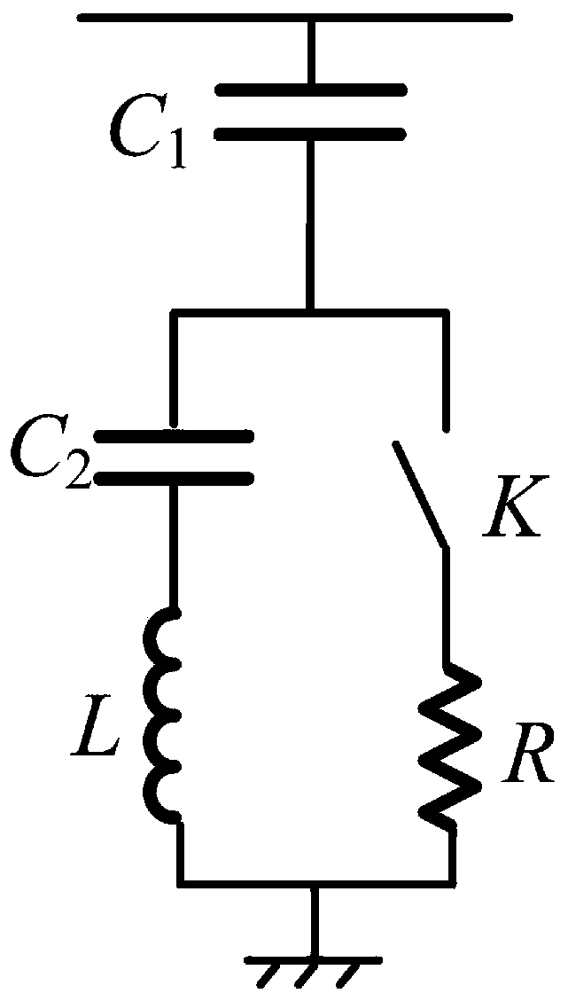
[0038] Such as figure 1 As shown, a C-type filter, including: the main capacitor C 1 , inductance L, second capacitance C 2 , switch K and resistor R.

[0039] When the switch K is turned off, the first connection relationship is formed: the main capacitor C 1 , inductance L and second capacitance C 2 connected in series to form a single-tuned filter for absorbing a single harmonic.

[0040] When the switch K is closed, the second connection relationship is formed: the resistor R is connected in parallel with the second capacitor C 2 The two ends of the series circuit formed with the inductor L form a C-type filter.

Embodiment 2

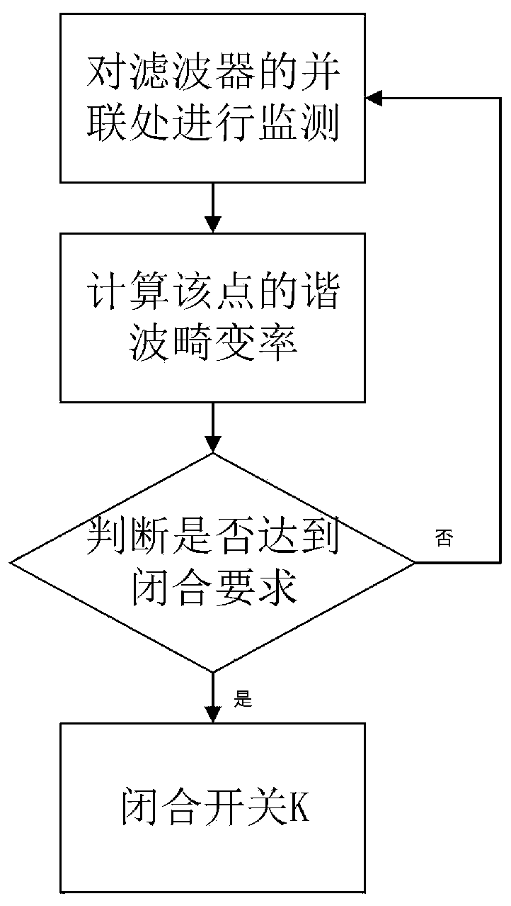
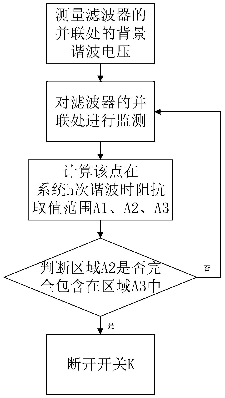
[0042] A switch control method, the switch control method is applied to a C-type filter described in Embodiment 1, and the harmonic voltage and harmonic current at this point are obtained by monitoring the parallel connection where the filter is installed, And based on this, the switch of the filter is controlled, and then the working state of the filter is switched. The switch control method includes the following content.

[0043]1. Determine the component C according to the non-resonant design method 1 , L, C 2 and R parameters. The resonance-free design method is cited from Resonance-Free Shunt Capacitors—Configurations, Design Methods and Comparative Analysis, Wilsun Xu, IEEE TRANSACTIONS ON POWER DELIVERY (2287).

[0044] S001: Determine C according to reactive power compensation requirements 1 , where Q F is the demand for reactive power compensation, V is the rated voltage, w 1 is the fundamental angular frequency.

[0045] S002: order Among them, the freque...

Embodiment 3

[0087] Such as Figure 5 As shown, a switch K is added to the C-type filter of the 138kV node SX, which is set as a switchable C-type filter designed by this patent, where the reactive power demand is 30MVar, the power frequency is 60Hz, and the tuning frequency is set to 180Hz. The harmonic voltage distortion rate before the filter is installed, that is, the background harmonic voltage distortion rate is shown in Table 1.

[0088] Table 1 Background harmonic voltage

[0089] Harmonic order 3 5 7 9 11 13 15 Background harmonic voltage distortion rate (%) 0.5 1.3 1.1 0.4 0.9 0.8 0.3 Harmonic order 17 19 21 23 25 27 29 Background harmonic voltage distortion rate (%) 0.6 0.4 0.2 0.2 0.2 0.2 0.2

[0090] The system impedance variation is mainly caused by C 11 and C 12 Therefore, considering four operating states, the corresponding system impedance is as follows Figure 6 and Figure 7 shown.

[0091] (1)Scenario 1: C ...


PUM


Abstract

The invention relates to the field of power systems, and particularly relates to a C-type filter and a switch control method thereof. The C-type filter comprises a main capacitor for reactive compensation, a resonance branch circuit formed by connecting an inductor and a capacitor in series, and a damping branch circuit formed by connecting a switch and a resistor in series. The resonance branch circuit and the damping branch circuit are connected in parallel and then are connected with the main capacitor in series. A disconnection moment determination method of an additional switch is proposed based on a harmonic standard; based on an equivalent circuit relationship between the filter and a power grid and a reference impedance range of the power grid, a closing moment determination methodof the additional switch is provided. Compared with a traditional C-type filter, by using the C-type filter of the invention, active losses can be reduced, heating is reduced, and a service life of equipment is prolonged.

Description

technical field [0001] The invention relates to the field of power systems, in particular to a C-type filter and a switch control method thereof. Background technique [0002] Parallel capacitors are one of the effective measures for reactive power compensation and have been widely used. However, the parallel capacitor may resonate with the system impedance to cause serious harmonic problems, causing large overvoltage and overcurrent in the power grid, causing electrical equipment failure or interfering with communication systems and other hazards. One of the basic ideas to solve this problem is to install a filtering device. Among them, the single-tuned filter is widely used because of its low cost and simple structure, but its design scheme is based on the premise that the system impedance is inductive. In actual engineering, especially in medium and high voltage systems, the system impedance changes greatly and has May be capacitive, ie harmonic resonances may still occ...

Claims


Application Information

Patent Timeline
Patent Type & Authority Applications(China)
IPC IPC(8): H02J3/01
CPCH02J3/01Y02E40/40
Inventor 王杨许双婷徐群伟吴俊黄弘扬楼伯良吕文韬马智泉李培陈锋
Owner SICHUAN UNIV
Learn More