
Automobile ECU quick testing device

A testing device and fast technology, applied in the directions of manipulators, program-controlled manipulators, chucks, etc., can solve the problems of unsatisfactory grasping effect and complex structure of circuit boards, improve grasping effect, expand swing range, and prevent falling. Effect

Inactive Publication Date: 2020-05-22
梁国莉
View PDF0 Cites 2 Cited by
  • Summary
  • Abstract
  • Description
  • Claims
  • Application Information

AI Technical Summary

Problems solved by technology

[0004] In the existing test production line, it is necessary for the manipulator to grab the circuit board to be tested and place it on the testing table for testing. The current manipulator structure is relatively complicated, and the effect of grasping the circuit board is not ideal, and there is room for improvement.

Method used


Image

  • Automobile ECU quick testing device
  • Automobile ECU quick testing device
  • Automobile ECU quick testing device

Examples


Embodiment 1

[0031] Refer below Figure 8 The basic composition of the automobile ECU of the embodiment of the present invention will be described.

[0032] In practical applications, due to the different configurations of the vehicles, the number of electronic control units is also different. Cars with low configuration and manual transmission generally have only one engine electronic control unit; cars with medium and high configuration, in addition to the engine electronic control unit, there are also automatic transmission electronic control units, anti-lock braking ABS electronic control units, and fully automatic air-conditioning electronic control units. Control unit, airbag electronic control unit, smart seat electronic control unit, central door control and other electronic control units, as many as a dozen, or even dozens of electronic control units. The composition mode of the electronic control unit on the car is the same, generally composed of sensors, ECU, and actuators.

...

Embodiment 2

[0049] Embodiment 2 is a further improvement to Embodiment 1.

[0050] In this embodiment, the testing device further includes a negative pressure generating device, which is electrically connected to the controller, that is, the controller can control the negative pressure of the negative pressure generating device.

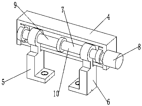
[0051] In this example, if Figure 5 with Image 6 As shown, the first clamping plate 5 is provided with a first accommodating cavity, and the first suction cup 19 is embedded and installed in the accommodating cavity. The first clamping plate 5 is provided with a first air hole 20, and the first air hole 20 is connected to the first air hole. The through hole 21 is connected, and the first air hole 20 is connected with the negative pressure generating device.

[0052] Specifically, the first clamping plate 5 is an L-shaped plate, the first clamping plate 5 has a first horizontal section and a first vertical section, the top of the first vertical section is pr...


PUM


Abstract

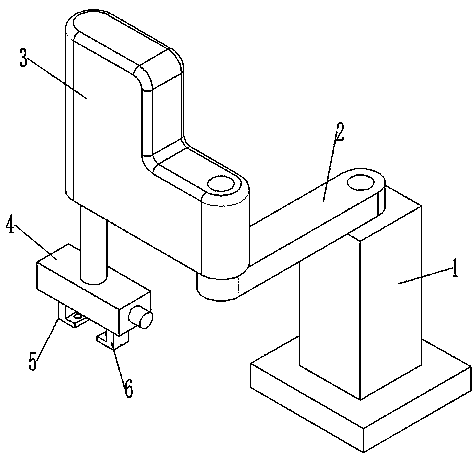
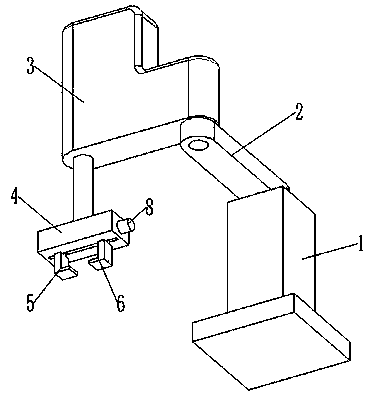
The invention relates to an automobile ECU quick testing device. The automobile ECU quick testing device comprises a manipulator, a detection platform and a controller. The manipulator comprises a supporting base, a first rotary arm, a second rotary arm, a first driving mechanism, a second driving mechanism, a third driving mechanism and a mounting base. The first rotary arm is rotatably connectedwith the supporting base. The first rotary arm is connected with the first driving mechanism. The second rotary arm is rotatably connected with the first rotary arm. The second rotary arm is connected with the second driving mechanism. The mounting base is connected with the third driving mechanism. The third driving mechanism is suitable for driving the mounting base to move vertically. A firstclamping plate, a second clamping plate and a fourth driving mechanism are mounted on the mounting base. The first clamping plate and the second clamping plate are arranged oppositely and are both connected with the fourth driving mechanism. The fourth driving mechanism is suitable for driving the first clamping plate and the second clamping plate to synchronously slide face to face or back to back. The first driving mechanism, the second driving mechanism, the third driving mechanism and the fourth driving mechanism are all electrically connected with the controller.

Description

technical field [0001] The invention relates to the field of detection devices, in particular to a quick test device for an automobile ECU. Background technique [0002] Automobile engine ECU (Engine Control Unit, engine controller) is an electronic device that controls the operation of various parts of the internal combustion engine. Safety. [0003] Although the automotive engine ECU has very high stability, the external interface of the sensor signal and the control actuator signal, the cable harness is prone to short circuit between signal lines, open circuit of signal line, open circuit of signal line, short circuit of signal to power supply, Faults such as short circuit of signal line to ground. In order to ensure that the ECU meets various technical indicators, its development process generally goes through steps such as design, simulation, rapid prototyping, code generation and software testing, hardware-in-the-loop, system calibration and testing. [0004] In the...

Claims


Application Information

Patent Timeline
Patent Type & Authority Applications(China)
IPC IPC(8): B25J9/12B25J15/00B25J15/06B25J15/08
CPCB25J9/12B25J15/0052B25J15/0616B25J15/08
Inventor 梁国莉
Owner 梁国莉
Learn More