High-power-capacity dual-band elliptical patch reflective array antenna

A reflect array antenna, dual-band technology, applied in antennas, antenna arrays, specific array feeding systems, etc., can solve the problems of restricting the application of dual-band patch antennas, low antenna power capacity, etc., to achieve easy phase adjustment, get rid of Limitation of Antenna Efficiency, Effect of Simplified Manufacturing Process

Pending Publication Date: 2020-05-22
SOUTHWEST JIAOTONG UNIV +1
View PDF0 Cites 2 Cited by
  • Summary
  • Abstract
  • Description
  • Claims
  • Application Information

AI Technical Summary

Problems solved by technology

Among them, the more representative single-layer dual-frequency antennas are: a slotted double-loop antenna that rotates the inner and outer rings to achieve high and low frequency phase adjustment [T.Smith, U.Gothelf, O.S.Kim, and O.Breinbjerg,"Design, Manufacturing, and Testing of a 20 / 30-GHzDual-Band Circularly Polarized Reflectarray Antenna, "IEEE Antennas WirelessPropag. Lett., vol.12, pp.1480-1483, 2013.], adding a rectangular ring that changes the side length of the rectangle for phase modulation Slotted Rectangular Patch Antenna [Z.Hamzavi-Zarghani and Z.Atlasbaf,"A New BroadBand Single-LayerDual-Band Reflectarray Antenna in X-and Ku-Bands,"IEEE Antennas WirelessPropag.Lett.,vol.14,pp.602 -605,2015.], Adjusting the length of the phase delay line to achieve high and low frequency phase modulation slotted circular patch plus dual phase delay line antenna [R.S.Malfajani and Z.Atlasbaf, "Design and Implementation of a Dual-Band Single Layer Reflectarray in X and K Bands,"IEEE Trans.Antennas Propag.,4425-4431,2014.], these antennas have achieved dual-band directional radiation, but due to the sudden patch structure, it is easy to cause local field concentration, resulting in antenna The low power capacity limits the application of dual-band patch antennas in the microwave field with high power capacity

Method used


Image

  • High-power-capacity dual-band elliptical patch reflective array antenna
  • High-power-capacity dual-band elliptical patch reflective array antenna
  • High-power-capacity dual-band elliptical patch reflective array antenna

Examples


Embodiment

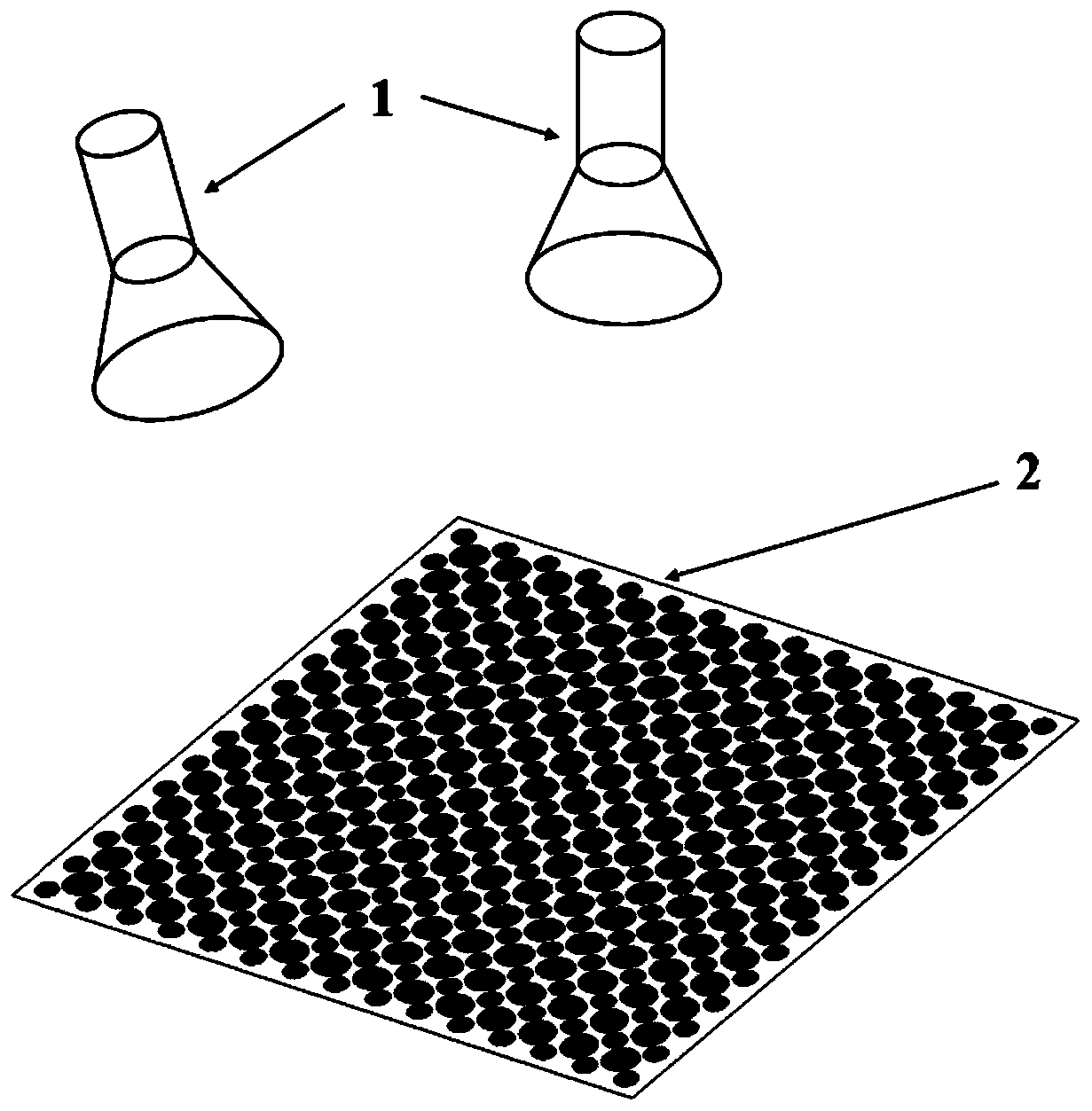
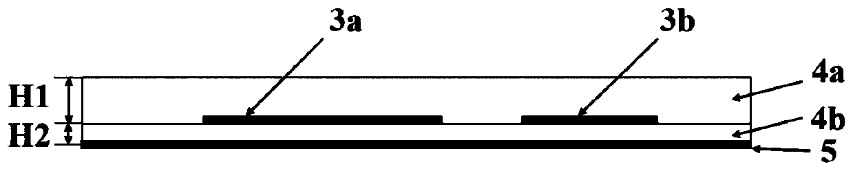
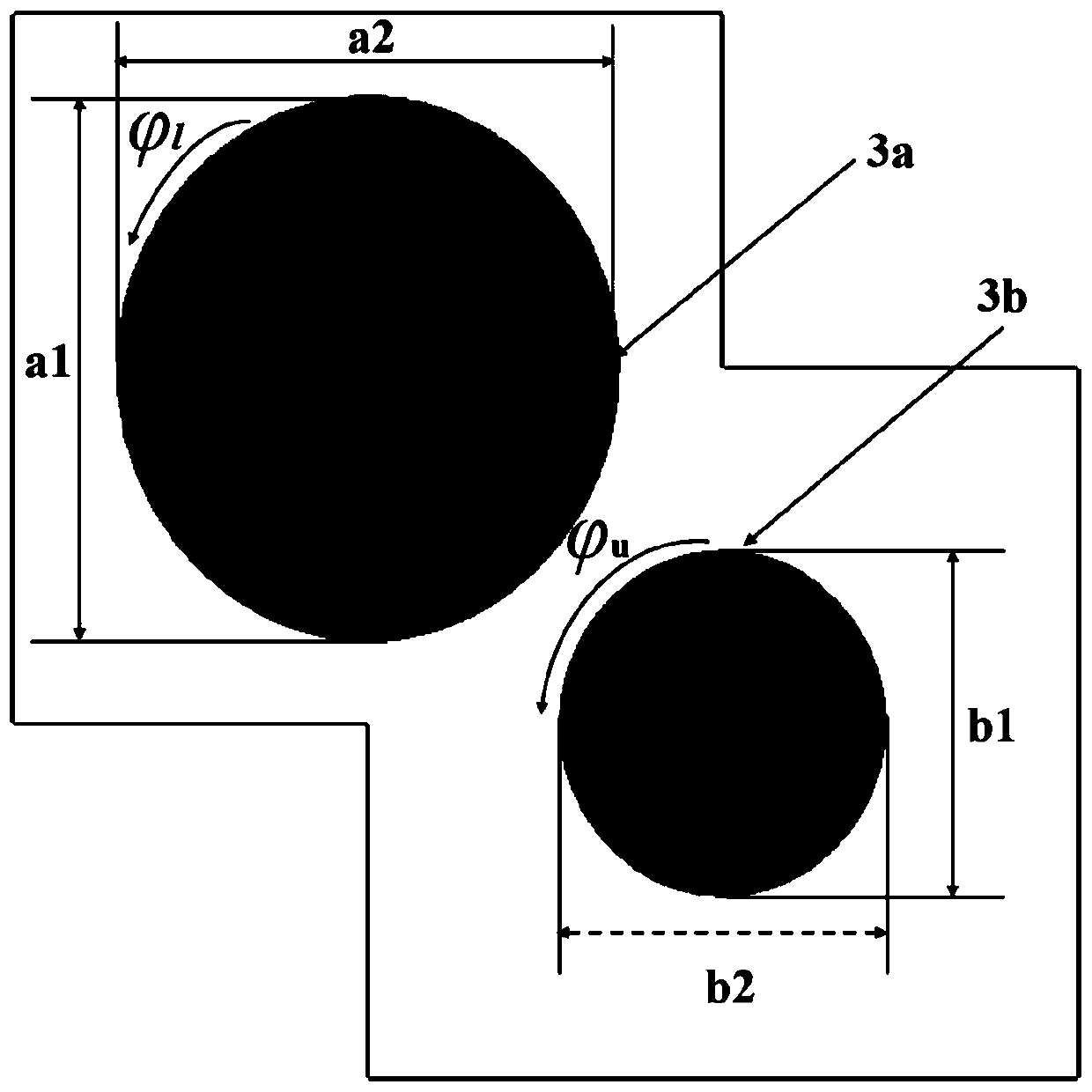
[0033] Please refer to Figure 1 ~ Figure 3, the present embodiment provides a dual-band elliptical patch reflectarray antenna with high power capacity, which includes a feed source 1 and a dual-band patch reflectarray 2, and the dual-band patch reflectarray 2 includes a dielectric plate and several radiation patches, The dielectric plate is provided with a reflective surface 5; the radiation patch is an elliptical patch, and includes a C-band radiation patch 3a and an X-band radiation patch 3b, each radiation patch is embedded in the same dielectric layer in the dielectric plate, and the C-band radiation patch The slices 3a and the X-band radiation patches 3b are arranged alternately.

[0034] In this embodiment, the feed source 1 is two horn antennas that work in the high and low frequency bands and can radiate circularly polarized waves respectively, which are placed above the dual-band patch reflectarray 2. The beam shape is a conventional pencil beam, and the C-band The ...


PUM

PropertyMeasurementUnit
lengthaaaaaaaaaa
lengthaaaaaaaaaa
thicknessaaaaaaaaaa

Abstract

The invention discloses a high-power-capacity dual-band elliptical patch reflective array antenna, and relates to the technical field of microwave communication. Compared with a traditional high-power-capacity antenna, the antenna adopts elliptical patches, which are different in frequency band size and are arranged in a staggered mode, as radiation patches. The limitation of low aperture utilization rate caused by narrow bandwidth of a traditional high-power-capacity antenna is overcome, the radiation of high-power-capacity microwaves can be realized in double frequency bands, the arrangementof a reflection array is flexible and easy to conform, the limitation of antenna efficiency caused by insertion loss is eliminated, and the efficiency of the antenna is higher. Compared with an existing dual-band patch reflective array antenna, the antenna adopts the elliptical patch antenna units as the radiation units, so field intensity concentration caused by patch slotting and seam protruding deformation structures is avoided. And meanwhile, the radiation patches are buried in the same dielectric layer in the dielectric plate, and the power capacity of the reflective array antenna is improved.

Description

technical field [0001] The invention relates to the technical field of microwave communication, in particular to a high-power-capacity dual-band elliptical patch reflective array antenna. Background technique [0002] The role of the high power capacity microwave antenna is to radiate the energy output by the high power microwave source into free space in a phased manner, and it is a key component of the high power microwave system. With the development and application of high-power microwave technology, high-power-capacity array antennas have been extensively studied. Generally speaking, these studies are mainly devoted to improving the antenna operating frequency [C.-W.Yuan, S.-R.Peng , T.Shu, Z.-Q.Li, and H.Wang,"Designs and Experiments of a Novel RadialLine Slot Antenna for High power Microwave Application,"IEEE Trans.AntennasPropag.,vol.61,no.10,pp. 4940-4946,2013.], Improving antenna power capacity [Y.Liang, J.Zhang, Q.Liu, and X.Li,"High power Dual-Branch Helical Ant...

Claims


Application Information

Patent Timeline
Patent Type & Authority Applications(China)
IPC IPC(8): H01Q1/38H01Q19/10H01Q21/00H01Q21/06H01Q21/30
CPCH01Q1/38H01Q19/104H01Q21/0006H01Q21/065H01Q21/30
Inventor 李相强孔歌星陈旭坤张健穹王庆峰
Owner SOUTHWEST JIAOTONG UNIV
Why Eureka
Try Eureka