Permanent magnet clutch and assembling method thereof

A clutch and permanent magnet technology, applied in the field of clutches, can solve problems such as inability to resist shocks, mechanical wear, and high noise

Active Publication Date: 2020-05-22
HEFEI UNIV OF TECH
View PDF5 Cites 0 Cited by
  • Summary
  • Abstract
  • Description
  • Claims
  • Application Information

AI Technical Summary

Problems solved by technology

[0003] In order to solve the technical problems of existing clutches such as mechanical wear, high noise, inability to withstand shocks, and the need for lubrication, the present invention provides a permanent magnetic clutch and its assembly method

Method used


Image

  • Permanent magnet clutch and assembling method thereof
  • Permanent magnet clutch and assembling method thereof
  • Permanent magnet clutch and assembling method thereof

Examples


Embodiment 1

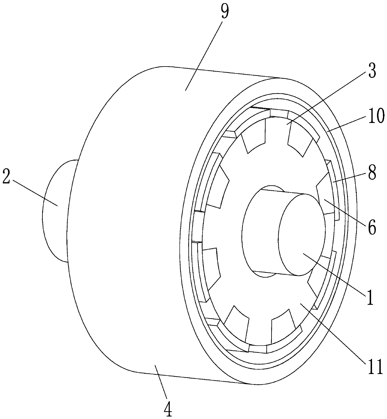
[0049] see figure 1 , this embodiment provides a permanent magnet clutch. Wherein, the permanent magnet clutch includes a driving disc 3 and a driven disc 4 . There is no direct contact between the driving disc 3 and the driven disc 4, and separation and coupling are realized through the action of a magnetic field, thereby realizing the clutch clutch process.

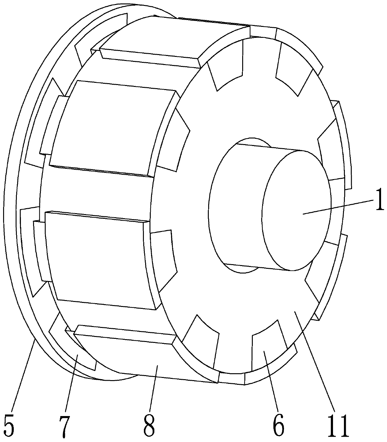
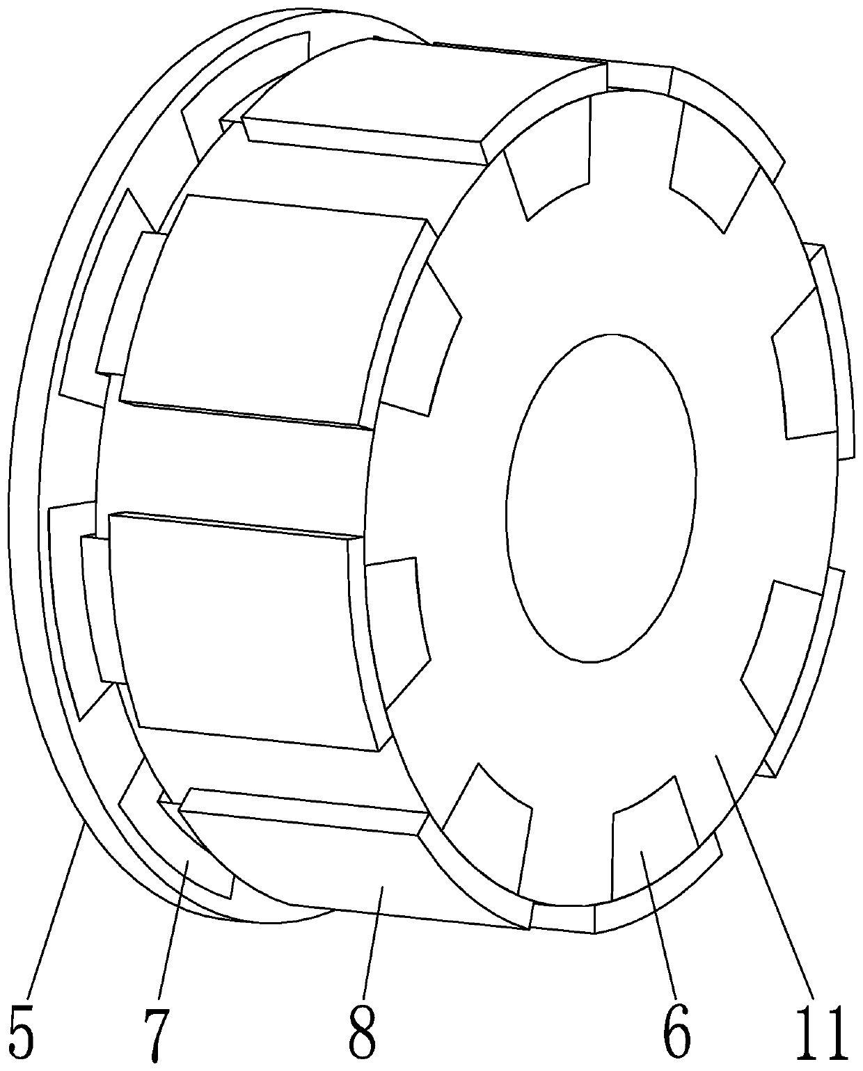
[0050] see figure 2 as well as image 3 , the driving disk 3 includes the driving inner shaft 1, the magnet fixed disk 5, the magnetic coil 1 7, the driving outer shaft 11, the back iron block 6 and the magnetic coil 2 8. The magnet fixed disk 5 is arranged coaxially with the driving inner shaft 1 and is fixedly connected. The active inner shaft 1 and the magnet fixing disk 5 can be connected by means of welding, clamping, bonding, etc., and can also be directly integrally formed with the magnet fixing disk 5 . The number of magnetic coils 17 is multiple, and a plurality of magnetic coils 7 are arranged in a circl...

Embodiment 2

[0074] This embodiment provides a permanent magnet clutch, which refines the structure on the basis of Embodiment 1. Wherein, the distance between the fixed magnet disk 5 and the active outer shaft 11 is d, and the value range of d is 2-4 mm. Of course, what needs to be explained here is that the smaller the value of the distance d, the better, but when the value of the distance d is too low, especially when the value of the distance d is lower than 2mm, the manufacturing cost of the permanent magnet clutch Can greatly improve, and this is because the magnetic circle two 8 and the corresponding magnetic circle one 7 are easy to attract together because the distance is too low.

[0075] In some embodiments, the preset distance d is 3 mm, and the distance d can be around 3 mm, and an optimal effect can be achieved at this time.

[0076] In other embodiments, the distance d is set according to the specific size of the clutch. For example, when the magnetism of the magnetic coil...

Embodiment 3

[0078] This embodiment provides a permanent magnet clutch, which refines the structure on the basis of Embodiment 1. Specifically, the projection planes of all magnetic coils one 7 on the end face of the active outer shaft 11 are located on the same projection sector, and the total projection area accounts for 70%-90% of the projection sector area. The total projected area of ​​all magnetic coils 2 8 on the outer wall of the active outer shaft 11 accounts for 70%-90% of the area of ​​the cylinder where the projected surface is located. What needs to be explained here is that, in this embodiment, the larger the value of these area ratios, the better the performance of the permanent magnet clutch. However, when the area ratio is greater than 90%, the gap will be too small, which is not conducive to the heat dissipation of the clutch when it is working, and then causes the magnetism of each magnetic ring to fade. Similarly, when the area ratio is less than 70%, the gap will be t...


PUM


Abstract

The invention discloses a permanent magnet clutch and an assembling method thereof. The permanent magnet clutch comprises a driving disc and a driven disc. The driving disc comprises a driving inner shaft, a magnet fixing disc, a plurality of first magnetic rings, a driving outer shaft, a plurality of back iron blocks and a plurality of second magnetic rings. The driven disc comprises a driven shaft, an outer sleeve and an inner sleeve. The magnet fixing disc is coaxial with the driving inner shaft, the first magnetic rings are installed on the magnet fixing disc, and the magnetic poles of every two adjacent first magnetic rings are arranged oppositely. The driving inner shaft is sleeved with the driving outer shaft, and the back iron blocks are embedded into the outer wall of the drivingouter shaft. The second magnetic rings are fixed to the driving outer shaft, and the magnetic poles of every two adjacent second magnetic rings are arranged oppositely. The second magnetic rings coverthe corresponding back iron blocks and are separated from the inner sleeve. The outer sleeve is sleeved outside the driving outer shaft, is fixed with the driven shaft and accommodates the driving disc. The inner sleeve is fixed on the inner wall of the outer sleeve. A master part and a slave part in the clutch are not in direct contact, so that mechanical abrasion of the clutch is avoided, the lubricating requirement is reduced, and the clutch has the advantages of vibration isolation and noise reduction.

Description

technical field [0001] The invention relates to a clutch in the technical field of machinery, in particular to a permanent magnet clutch, and also to an assembly method of the clutch. Background technique [0002] The clutch is similar to a switch, which engages or disengages the power transmission function. The active part and the driven part of the clutch mechanism can be temporarily separated, and can be gradually engaged, and it is possible to rotate relatively during the transmission process. Usually, the clutch is installed between the engine and the transmission, and is an assembly directly connected with the engine in the automobile drive train. The clutch is generally installed together with the flywheel set of the engine crankshaft, and it is a component that cuts off and transmits power between the engine and the vehicle transmission system. However, there is contact between the driving part and the driven part of the existing clutch, which may cause problems of ...

Claims


Application Information

Patent Timeline
Patent Type & Authority Applications(China)
IPC IPC(8): H02K49/10H02K15/03
CPCH02K15/03H02K49/106
Inventor 陈科史洪扬郑红梅房景仕郭亚军殷磊郑明睿
Owner HEFEI UNIV OF TECH
Why Eureka
Try Eureka