
Forming mold and method of planar ceramic target material

A technology for ceramic targets and forming molds, which is applied in ceramic forming machines, molds, mold auxiliary parts, etc., can solve the problems of difficulty in obtaining compactness, low green strength, and high price, and achieves reduction of hydraulic press molding and one-time molding. The effect of handling process, improving yield and material yield, and reducing the risk of cracking

Pending Publication Date: 2020-05-29
广州市尤特新材料有限公司
View PDF0 Cites 1 Cited by
  • Summary
  • Abstract
  • Description
  • Claims
  • Application Information

AI Technical Summary

Problems solved by technology

However, the green body obtained by the extrusion method contains a large amount of organic matter and water, which is difficult to sinter and compact; in-situ colloidal solidification molding also contains a large amount of organic matter and water, which is easy to crack when large-sized molding is dried, and it is difficult to obtain ultra-high Density; grouting molding has strict requirements on powder particle size and distribution, slurry and porous mold, and the drying control of green body is strict, which makes the technology difficult
[0003] At present, all the cold isostatic pressing methods are used for one-time molding by a hydraulic press, and then secondary molding by a cold isostatic pressing machine to obtain a green target. However, this molding method has the following disadvantages: 1) process It is cumbersome and needs to be molded first and then cold isostatic pressing; 2) Although the size of the green body after molding is regular, the density uniformity of the green body is poor. Equally, the target material will be bent, deformed or cracked; 3) The strength of the green body after one-time molding is not high, and it is particularly prone to cracking during handling; 4) The hydraulic press equipment used for cold isostatic pressing And molds are expensive, and the production process takes time, labor, electricity, etc.; 5) Currently, the molds used for forming are generally square, and it is difficult to make special-shaped molds. Special-shaped targets can only be cut later, and there will be more scraps waste

Method used


Image

  • Forming mold and method of planar ceramic target material
  • Forming mold and method of planar ceramic target material
  • Forming mold and method of planar ceramic target material

Examples


Embodiment 1

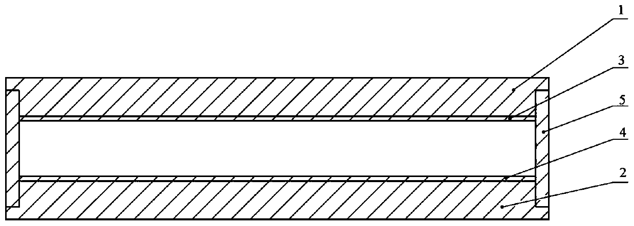
[0029] A molding die for a planar ceramic target, such as figure 1 As shown, it includes a steel mold, a flexible mold cover and a flexible plate. The steel mold includes an upper steel cover 1 and a lower steel cover 2. The upper steel cover 1 and the lower steel cover 2 are installed and combined to form a cavity body. The upper steel cover 1 and the lower steel cover 2 The material of the lower steel cover 2 is 45# steel, the two ends of the steel mold are provided with grooves, the flexible mold sleeve is installed in the groove, and is sealed with the steel mold, and the flexible plate is made of upper rubber The plate 3 and the lower rubber plate 4 are combined to form a hollow body placed in the steel mold. The cavity formed between the upper rubber plate 3, the lower rubber plate 4 and the flexible mold cover 5 is a powder filling cavity 6, and the powder filling cavity 6 is a square cavity; the material of the flexible mold cover 5 is polyurethane, and the Shore hardn...

Embodiment 2

[0037] A molding die for a planar ceramic target, such as figure 1 As shown, it includes a steel mold, a flexible mold cover and a flexible plate. The steel mold includes an upper steel cover 1 and a lower steel cover 2. The upper steel cover 1 and the lower steel cover 2 are installed and combined to form a cavity body. The upper steel cover 1 and the lower steel cover 2 The material of the lower steel cover 2 is 304 stainless steel. Both ends of the steel mold are provided with grooves. The flexible mold sleeve is installed in the groove and is sealed with the steel mold. The flexible plate is made of upper rubber The plate 3 and the lower rubber plate 4 are combined and placed in the cavity in the steel mold. The cavity formed between the upper rubber plate 3, the lower rubber plate 4 and the flexible mold cover 5 is a powder filling cavity 6, and the powder filling cavity 6 is a square cavity; the material of the flexible mold cover 5 is polyurethane, the Shore hardness is...

Embodiment 3

[0045] A molding die for a planar ceramic target, such as figure 1 As shown, it includes a steel mold, a flexible mold cover and a flexible plate. The steel mold includes an upper steel cover 1 and a lower steel cover 2. The upper steel cover 1 and the lower steel cover 2 are installed and combined to form a cavity body. The upper steel cover 1 and the lower steel cover 2 The material of the lower steel cover 2 is 45# steel, the two ends of the steel mold are provided with grooves, the flexible mold sleeve is installed in the groove, and is sealed with the steel mold, and the flexible plate is formed by the upper The rubber plate 3 and the lower rubber plate 4 are combined and placed in the cavity in the steel mold. The cavity formed between the upper rubber plate 3, the lower rubber plate 4 and the flexible mold sleeve 5 is a powder filling cavity 6, and the powder filling The cavity 6 is a square cavity; the material of the flexible mold cover 5 is polyurethane, and the Shore ...


PUM

PropertyMeasurementUnit
Shore hardnessaaaaaaaaaa

Abstract

The invention discloses a forming mold and method of a planar ceramic target material. The forming mold comprises a steel mold, flexible mold sleeves and a flexible plate. The steel mold comprises anupper steel cover and a lower steel cover. The upper steel cover and the lower steel cover are installed and combined to form an empty cavity. The flexible mold sleeves are mounted at the two ends ofthe steel mold and is in sealing fit with the steel mold. The flexible plate is formed by combining an upper rubber plate and a lower rubber plate and is arranged in the empty cavity of the steel mold. A cavity formed between the upper rubber plate, the lower rubber plate and the flexible mold sleeves serves as a powder filling cavity. The shore hardness of the flexible mold sleeves is 40-90, andthe shore hardness of the flexible plate is 20-60. The forming mold conducts cold isostatic pressing molding on granulation powder, a smooth ceramic target material green body with the regular size can be obtained, and the high-compactness target material can be obtained through sintering. The procedure of oil press molding is omitted in the ceramic material production process, input of equipmentand an oil press mold is reduced, and the risk that the ceramic target material green body cracks during transportation is also reduced.

Description

technical field [0001] The invention relates to the technical field of ceramic target forming, in particular to a forming die and method for a planar ceramic target. Background technique [0002] At present, the molding methods of ceramic rotating target body mainly include extrusion method, in-situ colloidal solidification molding, grouting molding and cold isostatic pressing molding. Extrusion, in-situ colloidal solidification molding and grouting molding can all be formed in near-net dimensions, and have certain advantages in making special-shaped parts. However, the green body obtained by the extrusion method contains a large amount of organic matter and water, which is difficult to sinter and compact; in-situ colloidal solidification molding also contains a large amount of organic matter and water, which is easy to crack when large-sized molding is dried, and it is difficult to obtain ultra-high Density; grouting molding has strict requirements on powder particle size ...

Claims


Application Information

Patent Timeline
Patent Type & Authority Applications(China)
IPC IPC(8): B28B7/00B28B3/00C04B35/453C04B35/622
CPCB28B3/003B28B7/0002B28B7/0097C04B35/453C04B35/622C04B2235/32C04B2235/602C04B2235/656C04B2235/6567
Inventor 雷雨赵明增周昭宇周志宏肖世洪
Owner 广州市尤特新材料有限公司
Learn More