Rotary machining die for forge piece machining

A technology for processing die and rotary type, which is used in manufacturing tools, metal processing equipment, forging/pressing/hammer devices, etc. It can solve the problems of prolonged forging time, forging errors, and reduced production efficiency, so as to reduce forging time and labor. Operation, the effect of improving the quality of forgings

CN111215569AInactive Publication Date: 2020-06-02张本松
0 Cites 1 Cited by

Patent Information

Authority / Receiving Office
CN · China
Patent Type
Applications(China)
Current Assignee / Owner
Publication Date
2020-06-02
Estimated Expiration
Not applicable · inactive patent

Smart Images

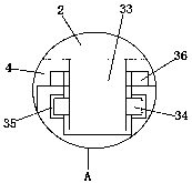
  • Figure 1
    Figure 1
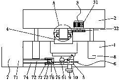
  • Figure 2
    Figure 2
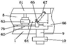
  • Figure 3
    Figure 3
Patent Text Reader

Abstract

The invention discloses a rotary machining die for forge piece machining. The rotary machining die for forge piece machining comprises a fixed die, a movable die, a rotating assembly, a forging hammer, a mounting groove, a die separating assembly, a cooling assembly, a first hydraulic rod, a water outlet pipe and a valve, and the rotating assembly is fixed to the outer wall of the bottom end of the movable die; and the rotating assembly comprises a motor, a first gear, a fixing rod, a first sliding block, a first sliding groove and a second gear, the fixing rod is welded and fixed to the outerwall of the middle of the bottom end of the movable mold, and the first sliding block is welded and fixed to the outer wall of one side of the fixing rod. According to the rotary machining die for forge piece machining, a rotating device is adopted for machining a curved surface structure, the rotating angle can be adjusted more finely through the motor, errors are reduced, the quality of a forgepiece is improved, a cooling device is further adopted, the forge piece can be rapidly cooled, the forging time is shortened, the production efficiency is improved, finally, a die separating device is utilized, therefore, the forge piece is separated from the die, the manual operation is reduced, and the working efficiency is improved.
Need to check novelty before this filing date? Find Prior Art

Description

technical field

[0001] The invention relates to the technical field of forging equipment, in particular to a rotary processing die for forging processing. Background technique

[0002] Forgings refer to workpieces or blanks obtained by forging and deforming metal blanks. By applying pressure to the metal blanks to produce plastic deformation, their mechanical properties can be changed; forgings can be divided into cold and cold according to the temperature of the blank during processing Forging Warm forging and hot forging; cold forging is generally processed at room temperature, hot forging is processed at a temperature higher than the recrystallization temperature of the metal blank, and molds are usually required for processing forgings, and molds are used for injection molding in industrial production , blow molding, extrusion, die-casting or forging forming, smelting, stamping and other methods to obtain various molds and tools for the required products; Composition, d...

Examples

Embodiment Construction

[0023] The following will clearly and completely describe the technical solutions in the embodiments of the present invention with reference to the accompanying drawings in the embodiments of the present invention. Obviously, the described embodiments are only some, not all, embodiments of the present invention. Based on the embodiments of the present invention, all other embodiments obtained by persons of ordinary skill in the art without making creative efforts belong to the protection scope of the present invention.

[0024] see Figure 1-5, the present invention provides a technical solution: a rotary processing mold for forging processing, including a fixed mold 1, a movable mold 2, a rotating assembly 3, a forging hammer 4, a mounting groove 5, a split mold assembly 6, a cooling assembly 7, The first hydraulic rod 8, the water outlet pipe 9 and the valve 10 are fixed with a rotating assembly 3 on the bottom outer wall of the movable mold 2; the rotating assembly 3 includ...