Welding movement control method, system and device, computer equipment and storage medium
A motion control and motion trajectory technology, applied in the fields of welding motion control methods, systems, devices, computer equipment and storage media, can solve the problems of reducing welding quality and affecting the welding accuracy of welding torch tracking, so as to improve welding quality and improve tracking. The effect of precision
- Summary
- Abstract
- Description
- Claims
- Application Information
AI Technical Summary
Problems solved by technology
Method used
Image
Examples
Embodiment 1
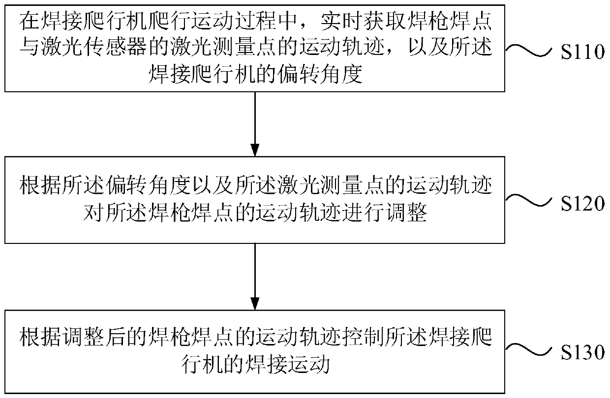
[0036] Figure 1a It is a flow chart of a welding motion control method provided by Embodiment 1 of the present invention. This embodiment is applicable to controlling the welding crawler to weld non-linear welds such as spheres. The method can be executed by a welding motion control device , the device can be realized by software and / or hardware, and generally can be integrated in computer equipment, and this computer equipment can be integrated on the welding crawler, such as PID (proportional-integral-derivative controller) as a welding crawler controller equipment, etc. Correspondingly, such as Figure 1a As shown, the method includes the following operations:
[0037] S110. During the crawling movement of the welding crawler, acquire in real time the movement track of the welding spot of the welding torch and the laser measurement point of the laser sensor, and the deflection angle of the welding crawler.
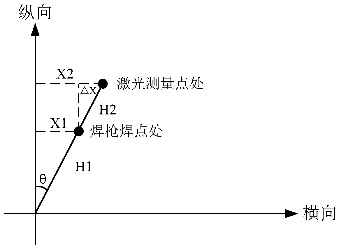
[0038] The laser sensor in the embodiment of the present inventi...
Embodiment 2
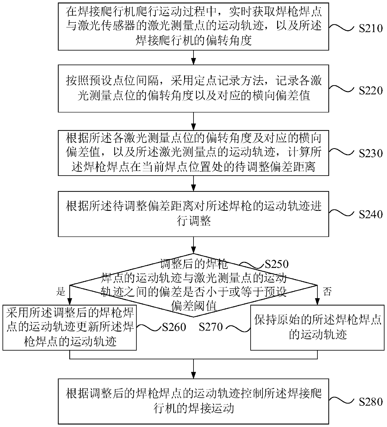
[0056] Figure 2a It is a flow chart of a welding motion control method provided in Embodiment 2 of the present invention. This embodiment is embodied on the basis of the above-mentioned embodiments. In this embodiment, it is given according to the deflection angle and the laser measurement The specific implementation manner of adjusting the movement trajectory of the welding torch welding point by the movement trajectory of the point, and verifying the adjusted movement trajectory of the welding torch welding point. Correspondingly, such as Figure 2a As shown, the method of this embodiment may include:
[0057] S210. During the crawling movement of the welding crawler, acquire in real time the movement track of the welding spot of the welding torch and the laser measurement point of the laser sensor, and the deflection angle of the welding crawler.
[0058] S220. Using a fixed-point recording method according to the preset point intervals, record the deflection angle of ea...
Embodiment 3
[0090] image 3 It is a structural schematic diagram of a welding motion control system provided by Embodiment 3 of the present invention, as shown in image 3 As shown, the structure of the welding motion control system includes: laser sensor 310, motion sensor 320, welding torch 330, welding crawler 340, cross slider 350 and data processing module 360, laser sensor 310, motion sensor 320, welding torch 330, cross The slider 350 and the data processing module 360 are installed on the welding crawler 350; the laser sensor 310, the motion sensor 320, the welding torch 330 and the cross slider 350 are connected in communication with the data processing module 360; wherein: the laser sensor 310 is used to detect the weld by laser Midpoint; the motion sensor 320 is used to obtain the deflection angle of the welding crawler in real time; the welding torch 330 is used to weld the weld seam; the cross slider 350 is used to adjust the lateral deflection distance of the welding torch...
PUM
 Abstract
Description
Claims
Application Information
 - R&D
- Intellectual Property
- Life Sciences
- Materials
- Tech Scout
- Unparalleled Data Quality
- Higher Quality Content
- 60% Fewer Hallucinations
Browse by: Latest US Patents, China's latest patents, Technical Efficacy Thesaurus, Application Domain, Technology Topic, Popular Technical Reports.
© 2025 PatSnap. All rights reserved.Legal|Privacy policy|Modern Slavery Act Transparency Statement|Sitemap|About US| Contact US: help@patsnap.com


