Piezoelectric MEMS ink-jet printing head and manufacturing method

An inkjet printing head and manufacturing method technology, applied in printing, inking devices, etc., can solve the problems of difficulty in ensuring the quality of the vibration plate, high potential risk of bonding, and many types of processes, so as to shorten the production cycle and improve the jetting performance , reducing the effect of process steps

Active Publication Date: 2020-06-02
NAT INST CORP OF ADDITIVE MFG XIAN
View PDF12 Cites 4 Cited by
  • Summary
  • Abstract
  • Description
  • Claims
  • Application Information

AI Technical Summary

Problems solved by technology

[0010] In order to solve the technical problems of the existing piezoelectric MEMS inkjet printheads, which have many production processes, high process risks, many types of processes involved in the production methods, difficulty in ensuring the quality of the vibration plate, and high potential risks caused by bonding, this paper The invention provides a piezoelectric MEMS inkjet printing head and its manufacturing method

Method used


Image

  • Piezoelectric MEMS ink-jet printing head and manufacturing method
  • Piezoelectric MEMS ink-jet printing head and manufacturing method
  • Piezoelectric MEMS ink-jet printing head and manufacturing method

Examples


Embodiment Construction

[0078] A preferred embodiment of the present invention will be described in detail below in conjunction with the accompanying drawings.

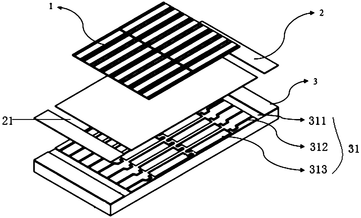
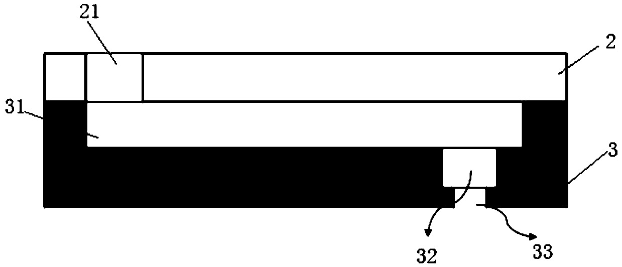
[0079] Such as figure 1 As shown, the piezoelectric inkjet printing head includes a piezoelectric ceramic layer 1, a vibrating plate 2, and a nozzle plate 3 from top to bottom, wherein both the vibrating plate 2 and the flow channel nozzle plate 3 are made of SOI silicon wafers. The vibration plate 2 is provided with an ink supply hole 21, and the nozzle plate 3 is provided with a pressure chamber 31, a drainage hole 32 and a nozzle hole 33 in sequence from top to bottom. The pressure chamber 31 includes two main ink channels arranged at the edge of the nozzle plate 3 311. Two groups of micro-channel structures arranged between the two main ink channels 311; the main ink channels 311 communicate with the ink supply holes 21, and each group of micro-channel structures includes connected filter channels 312 and flow channels 313, The filter c...


PUM

PropertyMeasurementUnit
thicknessaaaaaaaaaa
thicknessaaaaaaaaaa
thicknessaaaaaaaaaa

Abstract

The invention relates to a piezoelectric MEMS ink-jet printing head and a manufacturing method. An SOI silicon wafer is used as a processing raw material of a vibration plate and a nozzle plate; structures of a pressure cavity, a drainage hole and a nozzle hole of the printing head are all integrally designed on the nozzle plate; a metal thin film layer is manufactured before the pressure cavity is manufactured, and the metal thin film layer is used as a masking layer for ICP dry etching of the pressure cavity; in addition, the masking layer serves as a bonding metal layer when the vibration plate and the nozzle plate are bonded in the later period. Compared with the existing manufacturing method of the MEMS ink-jet printing head, the manufacturing method of the piezoelectric MEMS ink-jetprinting head has the advantages of fewer overall process steps, fewer related process types, higher dimensional accuracy and higher efficiency, the technical problems that an existing piezoelectric MEMS ink-jet printing head manufacturing method relates to a large number of process types, the quality of a vibration plate is difficult to guarantee, and potential risks generated by bonding are large are solved.

Description

technical field [0001] The invention belongs to the technical field of piezoelectric inkjet printing heads, and relates to a piezoelectric inkjet printing head and a manufacturing method. Background technique [0002] Droplet jet printing technology is a printing technology that generates a pressure difference between the ink chamber and the outside world through a certain extrusion method, causing the internal pressure of the nozzle to be greater than the external pressure, and then pushing the ink out of the nozzle to produce tiny ink droplets. [0003] Inkjet printheads are generally classified into piezoelectric inkjet printheads and thermal bubble inkjet printheads according to the way ink droplets are generated. The piezoelectric inkjet print head uses the deformation of the piezoelectric material to generate pressure to eject ink droplets; the thermal bubble inkjet print head generates bubbles in the ink by heating, and the expansion of the bubbles generates pressure ...

Claims


Application Information

Patent Timeline
Patent Type & Authority Applications(China)
IPC IPC(8): B41J2/14B41J2/16
CPCB41J2/14201B41J2/162B41J2/1628B41J2202/22
Inventor 王莉牛中会黄菲卢秉恒冯佳华
Owner NAT INST CORP OF ADDITIVE MFG XIAN
Why Eureka
Try Eureka