
Waste solvent recovery system and method

A recovery system and recovery method technology, applied in the field of waste solvent recovery system, can solve the problems of low product purity, waste solvent doped with impurities, etc., and achieve the effects of high purity and precision, reduced impurity content, and high use value

Pending Publication Date: 2020-06-05
SHANGHAI MORIMATSU PHARMA EQUIP ENG
View PDF0 Cites 1 Cited by
  • Summary
  • Abstract
  • Description
  • Claims
  • Application Information

AI Technical Summary

Problems solved by technology

[0004] However, after the waste solvent is processed by the recovery equipment, because it is only processed through one solvent recovery tower, the waste solvent is still doped with impurities, which in turn leads to a lower purity of the product separated from the waste solvent

Method used


Image

  • Waste solvent recovery system and method
  • Waste solvent recovery system and method

Examples


Embodiment 1

[0043] This embodiment provides a waste solvent recovery system, which can process and recover the waste solvent, and the purity of the product obtained after the waste solvent treatment is relatively high.

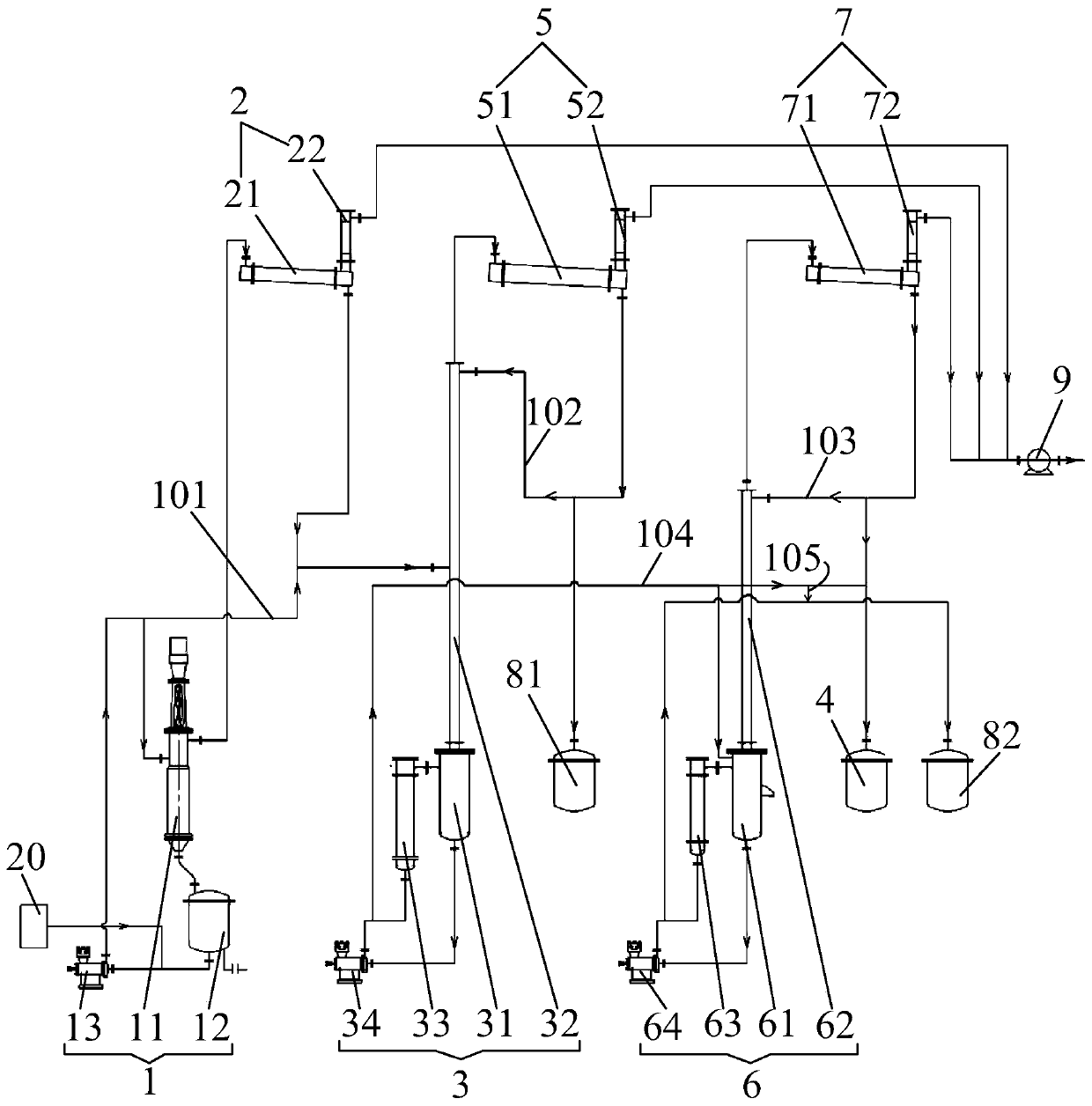
[0044] Such as figure 1 As shown, the waste solvent recovery system includes a thin film evaporation device 1, a first condensation device 2, a first distillation tower 3, a product tank 4, a second condensation device 5, and a first liquid receiving tank 81.

[0045] Wherein, the inlet of the thin film evaporation device 1 is in communication with the waste liquid device 20 containing waste solvent, and the thin film evaporation device 1 is used to remove high-boiling impurities, such as solid impurities, in the waste solvent. The inlet of the first condensing device 2 is communicated with the first outlet of the thin film evaporation device 1 so that the low boiling point substances in the thin film evaporation device 1 can enter the first condensing device 2. The first outl...

Embodiment 2

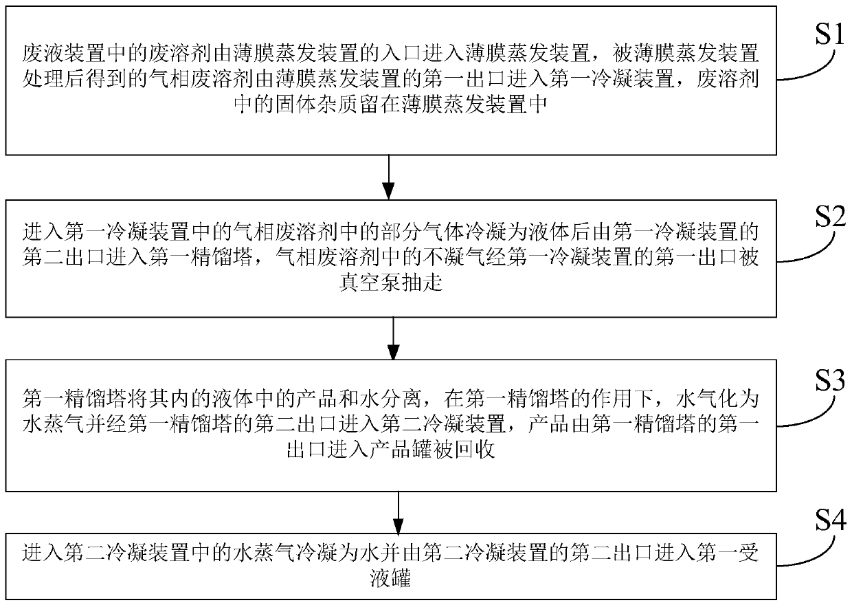
[0072] This embodiment also provides a waste solvent recovery method, which can be applied to the waste solvent recovery system in the first embodiment, such as figure 2 As shown, the waste solvent recovery method includes the following steps:

[0073] S1. The waste solvent in the waste liquid device enters the thin film evaporation device from the inlet of the thin film evaporation device, and the gas phase waste solvent obtained after being processed by the thin film evaporation device enters the first condensing device from the first outlet of the thin film evaporation device. The solids in the waste solvent Impurities remain in the thin film evaporation device.

[0074] S2. Part of the gas in the gas phase waste solvent entering the first condensing device is condensed into liquid and then enters the first rectification tower from the second outlet of the first condensing device, and the non-condensable gas in the gas phase waste solvent passes through the first condensing dev...


PUM


Abstract

The invention discloses a waste solvent recovery system and method, and belongs to the technical field of waste solvent recycling. The waste solvent recovery system comprises a film evaporation device, a first condensation device, a first rectification tower, a product tank and a second condensation device. The film evaporation device is communicated with a waste liquid device containing a waste solvent, and the first condensation device is respectively communicated with the film evaporation device and the vacuum pump; the first rectifying tower is communicated with the first condensing device, and the first rectifying tower is used for removing part of impurities in the condensed waste solvent; the product tank is communicated with the first rectifying tower and is used for containing thewaste solvent from the first rectifying tower; the second condensing device is respectively communicated with the first rectifying tower, the vacuum pump and the first liquid receiving tank, is communicated with the first liquid receiving tank and is used for condensing low-boiling-point impurities. The product treated by the waste solvent recovery system provided by the invention is relatively high in purity and relatively low in impurity content.

Description

Technical field [0001] The invention relates to the technical field of waste solvent recovery and utilization, in particular to a waste solvent recovery system and method. Background technique [0002] Waste solvents are usually liquids that lose their effectiveness due to being doped with other substances. They can include lithium battery NMP waste liquid, liquid crystal panel NMP waste liquid, etc. Recycling waste solvents can avoid waste of energy. [0003] In the prior art, recycling equipment is usually used to recycle waste solvents. The recovery equipment includes solvent recovery tower, reboiler, primary condenser, secondary condenser, heat exchanger, tower kettle pump and product tank. The settled waste solvent continuously enters the solvent recovery tower, the pressure at the top of the solvent recovery tower is 1KPa, the gas phase at the top of the tower is extracted into the primary condenser, and the residual oil is extracted from the tower bottom. The first-stage c...

Claims


Application Information

Patent Timeline
Patent Type & Authority Applications(China)
IPC IPC(8): B01D1/22B01D1/30B01D3/14B01D3/32B01D3/42B01D5/00
CPCB01D1/22B01D1/30B01D3/146B01D3/148B01D3/32B01D3/42B01D5/0036B01D5/0054B01D5/006B01D5/009
Inventor 陈浩周劲松陈学明李道全储志兵贺国伦
Owner SHANGHAI MORIMATSU PHARMA EQUIP ENG
Learn More