
Novel anti-drawing composite beam joint structure and manufacturing process

An anti-pulling, composite beam technology, applied in the direction of manufacturing tools, bridges, bridge parts, etc., can solve the problems of shear damage, prone to cracks, peeling, etc., and achieve the effect of preventing pulling, tight connection, and preventing cracking.

Pending Publication Date: 2020-06-05
浙江交工国际工程有限公司
View PDF0 Cites 1 Cited by
  • Summary
  • Abstract
  • Description
  • Claims
  • Application Information

AI Technical Summary

Problems solved by technology

As the main structural part of the bridge deck system, wet joint concrete bears heavy traffic loads on the bridge deck. The service life of wet joint concrete has a great impact on the normal operation of the bridge. Judging from the current status of the bridges that have been put into operation, in Cracking at the wet joints has become a common phenomenon. Most of the wet joints at the bridges are working with joints. What's more, after the pouring of the wet joint concrete of many highway bridges, there have been different degrees of cracking during the maintenance period. Water seepage, this phenomenon is more serious especially after rain, which has an adverse effect on the internal structure of the bridge and will lead to a decrease in the durability of the bridge; the traditional joint process fills the same grade of concrete between the butt-joint concrete slabs , prefabricated steel bars and concrete are jointly stressed. Under normal circumstances, the shear force and negative bending moment at the joint between the old and new concrete are often large, and the old and new concrete are under reciprocating loads for a long time, and they are prone to peeling off from each other; The traditional joint technology often does not set protective measures at the joint section. Under the action of the vehicle load, the upper and lower parts of the upper joint of the steel beam respond to the reciprocating compression load, and the prefabricated steel bars appear in-plane and out-of-plane bending. This kind of damage will have a fatal impact on the normal service of the steel-concrete composite beam, and the durability of the bridge cannot be guaranteed; when the composite beam is subjected to torque or local load or the negative bending moment of the support , Cracks are prone to appear between the old and new concrete. When the concrete slab rests for a short length, under the action of pressure load, the end of the concrete slab close to the upper flange of the steel beam is prone to vertical shear cracks or even shear failure, which will greatly reduce the durability of the structure. Safety and safety, under the action of negative bending moment and torque, the concrete slab above the steel beam will have a large vertical pullout force. The new and old concrete will produce vertical cracks under the action of this vertical pulling force, and even the new concrete will be pulled away. In combination with the shear force, the joint structure is often under complex stress. It has great potential safety hazards; China's "Code for Design of Steel-Concrete Composite Bridges GB50917-2013" clearly stipulates that "when the bridge deck uses prefabricated reinforced concrete bridge decks, measures should be taken to make the prefabricated slabs and steel beams closely bonded to meet the waterproof requirements. At the same time, the "Code for Design and Construction of Highway Steel-Concrete Composite Bridges JTG / T D64-01-2015" also stipulates in the durability design of the steel-concrete contact surface that "the contact surface should be prevented from the aspects of concrete configuration, structural requirements and construction technology. The gap between the steel beam and the concrete slab cannot meet the requirement of tightness and no void under the reciprocating load of the joint of the traditional technology

Method used


Image

  • Novel anti-drawing composite beam joint structure and manufacturing process
  • Novel anti-drawing composite beam joint structure and manufacturing process
  • Novel anti-drawing composite beam joint structure and manufacturing process

Examples


Embodiment Construction

[0044] The present invention will be further described below in conjunction with the accompanying drawings.

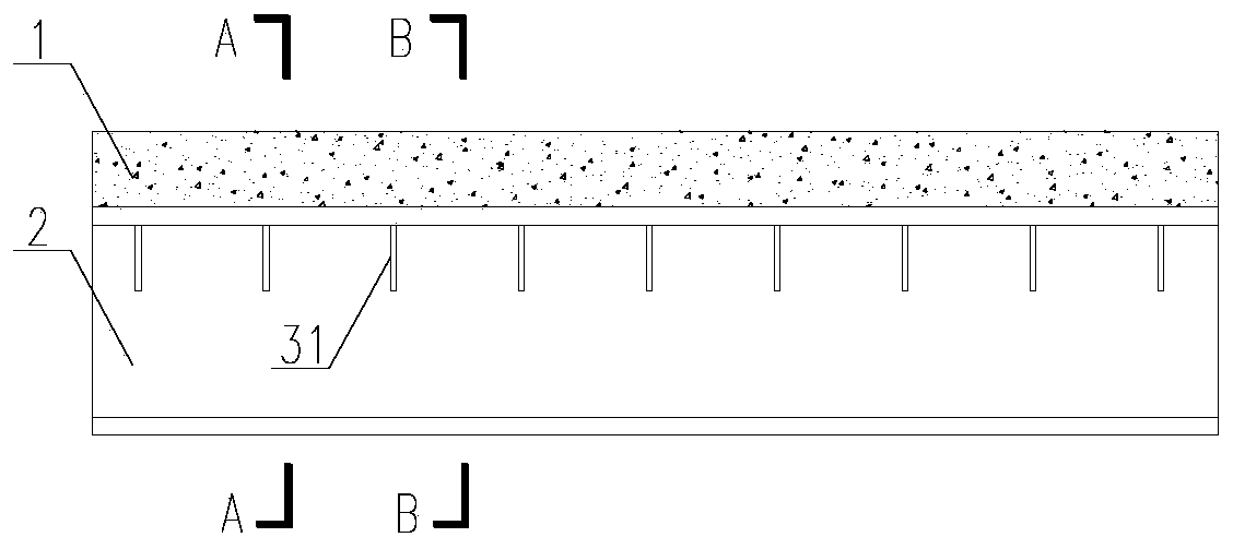
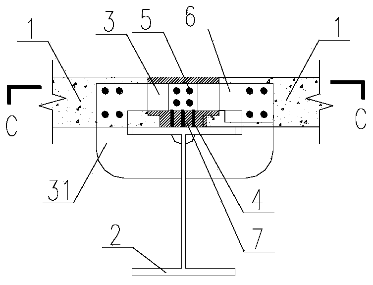
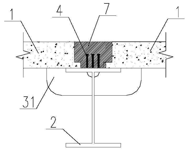
[0045] refer to Figure 1 to Figure 6 , a new type of anti-pull composite beam joint structure, the joint structure includes a concrete slab 1, a steel beam 2, a pre-embedded plate 3, an overhanging connection anti-pull head 31, a stud shear key 4, a connection Reinforcing bar 5, connecting bar hole 51, stress bar 6, stress bar hole 61 and polymer mortar 7.

[0046] The upper surface of the upper flange of the steel beam 2 is provided with a stud shear force key 4; the steel beam 2 and the stud shear force key 4 are both made of weathering steel, and the stud shear force key 4 is welded to the upper flange of the steel beam 2 by a welding process The upper surface; the concrete slab 1 is arranged on the steel beam 2, and the steel girder 2 is the support of the concrete slab 1; During the installation process, the concrete slab 1 rests on the steel girder 2, and a U-s...


PUM


Abstract

The utility model discloses a novel anti-drawing composite beam joint structure. A stud shear key is arranged on the upper surface of an upper flange of the steel beam, the concrete slab is arranged on the steel beam, the steel beam is a support of the concrete slab, a plurality of embedded part plates are arranged on a connecting edge of the concrete slab, each embedded part is divided into an embedded part, an exposed part and an outwards-extending connecting anti-drawing head, and the embedded parts are located in the concrete slab. The embedded part of the embedded part plate is provided with a stressed steel bar hole, and the position of the stressed steel bar hole corresponds to the position of a stressed bar in the concrete plate; connecting steel bar holes are formed in the exposedparts of the embedded part plates, and the sizes of the connecting steel bar holes need to correspond to those of connecting steel bars; a U-shaped hole is formed between the concrete slab and the steel beam, and the U-shaped hole is filled with polymer mortar. The overall stress performance of the composite beam bridge, the tightness between the top flange of the steel beam and concrete, the vertical shear resistance and durability between new concrete and old concrete, the anti-drawing performance and shear resistance between steel and concrete and the bearing capacity of a joint at the manufacturing position are improved.

Description

technical field [0001] The invention relates to the details of bridge engineering and building structure engineering and the fields of structure and construction, in particular to a novel tensile-resistant composite beam joint structure and a manufacturing process. Background technique [0002] In recent years, with the development of my country's economy, the country has paid more and more attention to the research and development and promotion of composite structures. In order to reduce the hoisting weight of the prefabricated steel-concrete composite girder and facilitate transportation, the prefabricated steel-concrete composite girder bridge is generally provided with joints at the adjacent main beams. After the prefabricated components are assembled, the joint concrete is poured to form a whole. During bridge operation, wet joints are one of the most susceptible parts of precast concrete decks to disease. Wet joints are mainly composed of steel members and concrete, b...

Claims


Application Information

Patent Timeline
IPC IPC(8): E01D19/12E01D21/00B28B23/02
CPCB28B23/02E01D19/125E01D21/00
Inventor 奚兵杨雄沈兴承葛东亮徐康
Owner 浙江交工国际工程有限公司
Learn More