Prefabricated laminated member and production method thereof, and prefabricated laminated wall and construction method thereof
A technology of superimposing components and walls, applied to building components, walls, building structures, etc., to achieve the effects of reducing component weight, high overall strength, and increasing seepage paths
- Summary
- Abstract
- Description
- Claims
- Application Information
AI Technical Summary
Problems solved by technology
Method used
Image
Examples
Embodiment 1
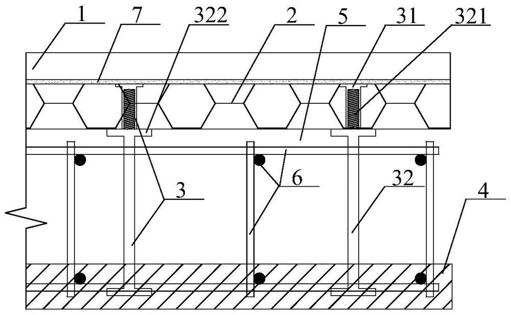
[0110] This embodiment provides a prefabricated laminated member, such as figure 1 , 2 ,include:
[0111] Interconnected veneer 1 and insulation board 2. The decorative panel 1 is preferably made of lightweight materials such as foamed ceramics; the decorative panel is a finished hard decorative panel with a fire rating of A1, which also has good thermal insulation performance and high strength, and can further improve the thermal insulation effect when integrated with the thermal insulation board. The insulation board 2 is preferably a class A insulation board. There are several specific connection methods. figure 1 shown in 7 connected by bonding mortar. Use other adhesives, bolted joints, special joints ( image 3 display) and other connections are available. Reinforcing cage 6 connected to inner blade 4. The inner blade 4 can be made of concrete, and the connection with the reinforcement cage 6 can be by directly fixing the reinforcement cage 6 in the concrete when ...
Embodiment 2
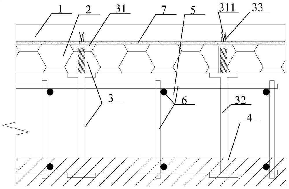
[0120] like figure 2 , this embodiment provides another prefabricated composite member, the decorative panel 1 and the insulation board 2 connected to each other; the reinforcement cage 6 connected with the inner blade 4; the cavity 5 is formed between the insulation board 2 and the inner blade 4; A plurality of connecting assemblies 3 connecting the thermal insulation board 2 and the inner blade 4 to each other.
[0121] This example and figure 1 The difference between the specific structures shown is that the connection assembly 3 also includes an expansion tube 33 embedded in the decorative panel 1, and an overhang 311 disposed at one end of the built-in component 31. The overhang 311 extends into the expansion tube 33 and expands and expands. The diameter of the pipe 33 to connect the decorative panel 1 and the insulation panel 2. The combination of the outrigger 311 and the expansion tube 33 may not rely on the adhesive mortar 7 or the claw-type connector 8 ( image 3...
Embodiment 3
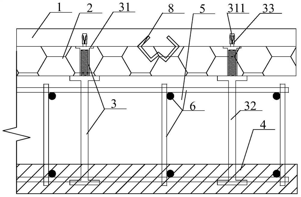
[0128] like image 3 , this embodiment provides another kind of prefabricated composite member, the decorative panel 1 and the insulation board 2 connected to each other; the reinforcement cage 6 connected with the inner blade 4; the cavity 5 is formed between the insulation board 2 and the inner blade 4; A plurality of connecting assemblies 3 connecting the thermal insulation board 2 and the inner blade 4 to each other.
[0129] Compared with the first embodiment, the present embodiment and figure 1 The difference between the specific structures shown is that the decorative panel 1 and the thermal insulation panel 2 are connected by a plurality of claw-type connectors 8 . If the insulation board 2 is a finished product, it is more suitable for bonding the mortar 7 for connection; if the insulation board 2 is poured with slurry, it is more suitable for the connection of the claw-type connector 8 . After connecting the claw-shaped connector 8 to the decorative panel 1, direct...
PUM
 Abstract
Description
Claims
Application Information
 - R&D
- Intellectual Property
- Life Sciences
- Materials
- Tech Scout
- Unparalleled Data Quality
- Higher Quality Content
- 60% Fewer Hallucinations
Browse by: Latest US Patents, China's latest patents, Technical Efficacy Thesaurus, Application Domain, Technology Topic, Popular Technical Reports.
© 2025 PatSnap. All rights reserved.Legal|Privacy policy|Modern Slavery Act Transparency Statement|Sitemap|About US| Contact US: help@patsnap.com


