
Sequential control loop for servo motor to drive constant delivery pumps

A servo motor, sequential control technology, applied in pump control, machine/engine, mechanical equipment, etc., can solve the problems of shortening the service life of the hydraulic system, increasing the temperature of the hydraulic transmission system, low energy conversion efficiency, etc., to reduce the heat generation. , The effect of stable operation and not easy operation

Pending Publication Date: 2020-06-05
NINGBO CHUANGLI HYDRAULIC MACHINERY MFG CO LTD
View PDF0 Cites 0 Cited by
  • Summary
  • Abstract
  • Description
  • Claims
  • Application Information

AI Technical Summary

Problems solved by technology

[0006] Generally, the actuators of the hydraulic transmission system of the rolling mill require a large flow rate when starting, and the demand is small under normal working conditions, and because there is a certain internal leakage in the hydraulic transmission system, in order to keep the pressure of the hydraulic system stable, no matter which of the above As the power source, a single pump operates under high pressure and low flow under normal working conditions, and the excess hydraulic oil flows back to the oil tank through the overflow valve, which will cause a large amount of power loss, resulting in low energy conversion efficiency and low power loss. Converting into heat will cause the temperature of the hydraulic transmission system to rise and shorten the service life of the hydraulic system. Therefore, it is still necessary to further improve the power source

Method used


Image

  • Sequential control loop for servo motor to drive constant delivery pumps

Examples


Embodiment Construction

[0023] The present invention will be further described in detail below in conjunction with the accompanying drawings and embodiments.

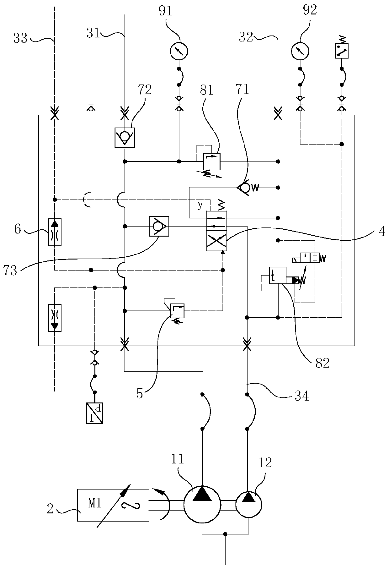
[0024] Such as figure 1 As shown, the sequential control loop for servo motor-driven quantitative pump involved in this embodiment includes servo motor 1, double pump, oil outlet pipeline 31, oil return pipeline 32, oil unloading pipeline 33, branch 34, replacement One-way valve 4, sequence valve 5, damper 6, first one-way valve 71, second one-way valve 72, third one-way valve 73, first relief valve 81, second relief valve 82, first pressure Gauge 91 and second pressure gauge 92.

[0025] Such as figure 1 As shown, the duplex pump is driven by servo motor 1. The duplex pump includes a first quantitative pump 11 and a second quantitative pump 12 coaxially arranged, the oil outlet of the first quantitative pump 11 communicates with the oil outlet pipeline 31, and the oil outlet of the second quantitative pump 12 passes through a branch 34 co...


PUM


Abstract

The invention relates to a sequential control loop for a servo motor to drive constant delivery pumps. The sequential control loop is characterized by comprising an oil outlet pipeline, an oil returnpipeline and duplex pumps driven by the servo motor, the duplex pumps comprise the first constant delivery pump and the second constant delivery pump which are coaxially arranged, an oil outlet of thefirst constant delivery pump is communicated with the oil outlet pipeline, and an oil outlet of the second constant delivery pump is communicated with the oil outlet pipeline through a branch; and areversing valve with an oil inlet, a first working port and an oil return port is arranged on the branch, the oil inlet of the reversing valve is communicated with the oil outlet of the second constant delivery pump, the first working port of the reversing valve is communicated with the oil outlet pipeline, the oil return port of the reversing valve is communicated with the oil return pipeline, inthe state that the oil pressure of the oil outlet pipeline is lower than the set pressure, the oil inlet of the reversing valve is communicated with the first working opening, and in the state that the oil pressure of the oil outlet pipeline reaches the set pressure, the oil inlet of the reversing valve is communicated with the oil return port. The sequential control loop for the servo motor to drive the constant delivery pumps is more energy-saving and can reduce the heating amount of a hydraulic system.

Description

technical field [0001] The invention relates to the technical field of power systems, in particular to a sequential control circuit for a servo motor driving a quantitative pump. Background technique [0002] The hydraulic transmission system of the rolling mill includes five parts: power components, executive components, control components, auxiliary components (accessories) and working media. The power components convert the mechanical energy of the power machine into the pressure energy of the working medium, and the control components control the pressure and flow of the working medium. And the direction of flow, and the pressure energy of the working medium is transmitted to the actuator, and the actuator converts the pressure energy of the working medium into mechanical energy, output force and speed (that is, linear motion), or torque and speed (that is, rotary motion). Among them, the power element and the power machine together constitute the power source of the hyd...

Claims


Application Information

Patent Timeline
Patent Type & Authority Applications(China)
IPC IPC(8): F04B49/00F04B49/22
CPCF04B49/002F04B49/22
Inventor 龚群韩冰励之渊林永泽龙伟
Owner NINGBO CHUANGLI HYDRAULIC MACHINERY MFG CO LTD
Learn More