Air cooling and liquid cooling combined battery heat dissipation device and method

A heat-dissipating device and a combined technology, applied in battery circuit devices, circuit devices, secondary batteries, etc., can solve the problems of inability to control the maximum temperature of the battery pack at 50°C, decrease in charge and discharge capacity, and low thermal conductivity, so as to make up for it. The effect of uneven heat dissipation, energy saving and low cost

Active Publication Date: 2020-06-05
JIANGSU UNIV
View PDF3 Cites 12 Cited by
  • Summary
  • Abstract
  • Description
  • Claims
  • Application Information

AI Technical Summary

Problems solved by technology

When the ambient temperature is too low, the movement rate of conductive ions will decrease, the internal resistance of the lithium-ion battery will increase rapidly, and the charge and discharge capacity will drop significantly. When the temperature is high, a series of chemical reactions accumulate and strengthen each other, generating a large amount of heat, which is easy to cause thermal runaway and lead to safety accidents such as fire and deflagration
At present, the cooling methods of lithium-ion battery thermal management systems mainly include air cooling (air cooling), liquid cooling (liquid cooling) and phase change material cooling. Air cooling has the advantages of simple structure and convenient maintenance, but it cannot Control the maximum temperature of the battery pack within 50°C; the existing liquid cooling structure has a better cooling effect than air cooling, but the overall structure is more complicated and the system consumes more energy; phase change material cooling has its own thermal conductivity Disadvantages of small size and large amount of heat absorption at the phase transition point of the material, and volume expansion after the phase transition of the material
In the current battery thermal management technology, there are few studies on combining air cooling and liquid cooling for effective control to save energy

Method used


Image

  • Air cooling and liquid cooling combined battery heat dissipation device and method
  • Air cooling and liquid cooling combined battery heat dissipation device and method
  • Air cooling and liquid cooling combined battery heat dissipation device and method

Examples


Embodiment Construction

[0022] The present invention will be further described below in conjunction with the accompanying drawings and specific embodiments, but the protection scope of the present invention is not limited thereto.

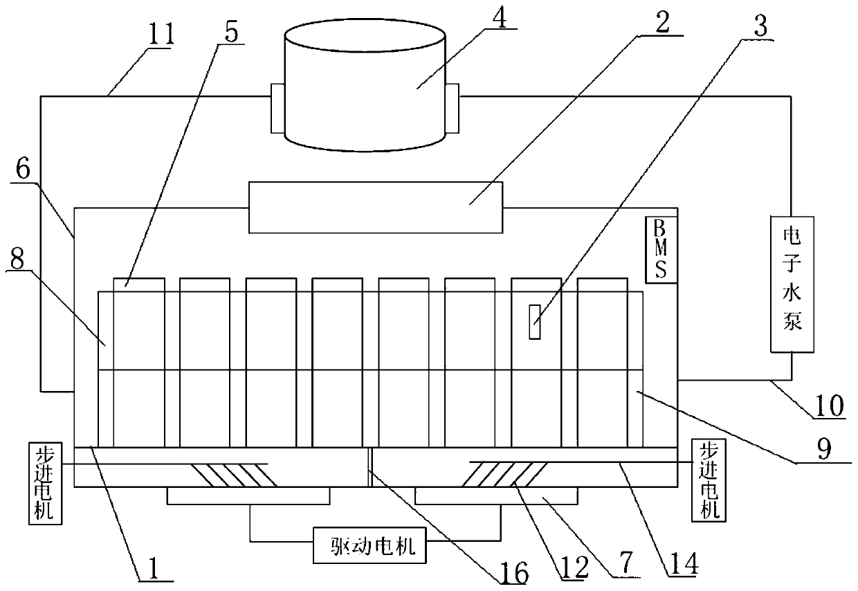
[0023] Such as figure 1 As shown, the heat dissipation device of the present invention includes a battery case 6 , a heat dissipation assembly, a battery module set in the battery case 6 and a BMS (Battery Management System, battery management system) installed in the battery case 6 .

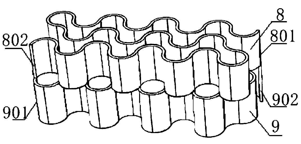
[0024] A number of single cells 5 with battery covers in the battery case 6 are arranged in a rectangular array to form a battery module. The lower part of the battery case 6 is provided with a substrate 1 for placing the battery module; the surface of the substrate 1 is not in contact with the single cells. 5 The contact part is provided with several through holes to facilitate heat dissipation. The cooling assembly includes an exhaust fan 2, a temperature sensor 3, a two-way S-shaped su...


PUM


Abstract

The invention provides an air cooling and liquid cooling combined battery heat dissipation device and method, and belongs to the technical field of automobile battery heat management. According to thewhole heat dissipation device, a bidirectional surrounding liquid cooling pipe is arranged at the periphery of a battery module, and a cooling fan is arranged at the bottom of a battery box body, sothat air cooling and liquid cooling are combined to dissipate heat of the battery module; meanwhile, the cooling fan driving motor and the electronic water pump are controlled through the BMS, different heat dissipation modes can be selected according to the battery module temperature detected in real time, the rotating speed of the cooling fan and the flow of a cooling liquid inlet can be controlled in real time according to the temperature, energy is saved, and heat dissipation is efficient; and the heat dissipation device is further provided with a wind pendulum and an exhaust fan for auxiliary heat dissipation, and the heat dissipation effect is further improved.

Description

technical field [0001] The invention belongs to the technical field of thermal management of automobile batteries, and in particular relates to a battery cooling device and method combining air cooling and liquid cooling. Background technique [0002] As the main power source of new energy vehicles, lithium-ion batteries have the advantages of high working voltage, high energy density, long cycle life and environmental friendliness, but at the same time, lithium-ion batteries are very sensitive to temperature. Studies have shown that the optimal operating temperature of lithium-ion batteries is 20-40°C, and the temperature difference (ΔT) in the battery pack should be controlled below 5°C. When the ambient temperature is too low, the movement rate of conductive ions will decrease, the internal resistance of the lithium-ion battery will increase rapidly, and the charge and discharge capacity will drop significantly. When the temperature is high, a series of chemical reaction...

Claims


Application Information

Patent Timeline
Patent Type & Authority Applications(China)
IPC IPC(8): H01M10/613H01M10/42H01M10/625H01M10/633H01M10/635H01M10/6551H01M10/6557H01M10/6563H01M10/6568
CPCH01M10/613H01M10/625H01M10/633H01M10/635H01M10/6551H01M10/6563H01M10/6568H01M10/4257H01M10/6557H01M2010/4271H01M2010/4278Y02E60/10
Inventor 栗欢欢王毅洁王亚平竺玉强陈龙江浩斌
Owner JIANGSU UNIV
Why Eureka
Try Eureka