Heat exchanger, heat exchange system and method for deep recovery of flue gas waste heat of gas boiler

A gas-fired boiler and flue gas waste heat technology, which is applied in the field of flue gas waste heat recovery, can solve the problems of large footprint, long recovery cycle, and high investment, and achieve the effects of small footprint, low cost, and high latent heat recovery rate

Active Publication Date: 2020-06-09
SHANDONG UNIV
View PDF11 Cites 1 Cited by
  • Summary
  • Abstract
  • Description
  • Claims
  • Application Information

AI Technical Summary

Problems solved by technology

However, the method of absorption heat pump has high investment, large floor

Method used


Image

  • Heat exchanger, heat exchange system and method for deep recovery of flue gas waste heat of gas boiler
  • Heat exchanger, heat exchange system and method for deep recovery of flue gas waste heat of gas boiler
  • Heat exchanger, heat exchange system and method for deep recovery of flue gas waste heat of gas boiler

Examples


Embodiment

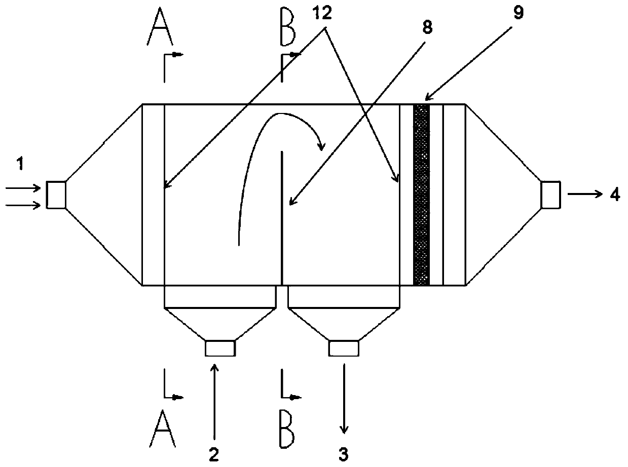
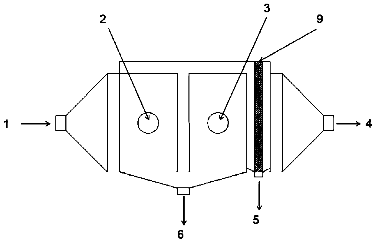
[0065] Such as figure 1 and Figure 5 As shown, a heat exchanger for deep recovery of waste heat from flue gas of a gas-fired boiler, a cylindrical shell, both ends of which are necked structures, forming a flue gas inlet 1 and a flue gas outlet 4;

[0066] Two fixing plates (the first fixing plate and the second fixing plate) 12 are respectively arranged on the cross-sections of the two ends of the cylindrical shell, and are sealed with the inner wall of the cylindrical shell;

[0067] An air inlet 2 and an air outlet 3 are arranged on the side wall of the cylindrical shell between the two fixing plates 12, and a baffle 8 is arranged between the air inlet 2 and the air outlet 3, and the baffle 8 is connected to the heat exchange tube. It is vertically arranged, and one side is sealed with the cylindrical shell, and a certain distance is left between the other side and the cylindrical shell so that the air can pass through smoothly. The size of the baffle plate 8 is smaller t...


PUM


Abstract

The invention discloses a heat exchanger, heat exchange system and method for deep recovery of flue gas waste heat of a gas boiler. The heat exchanger includes a cylindrical shell, a first fixing plate, a second fixing plate, a plurality of heat exchange tubes and liquid distribution tubes; both ends of the cylindrical shell are each of a necking-down opening structure, and a flue gas inlet and aflue gas outlet are formed; the first fixing plate and the second fixing plate are separately arranged on the cross-sections of both ends of the cylindrical shell, and are sealed with the inner wall of the cylindrical shell; an air inlet and an air outlet are formed in the positions, between the first fixing plate and the second fixing plate, on the side wall of the cylindrical shell, and a baffleplate is arranged between the air inlet and the air outlet; both ends of the heat exchange tubes are separately nested in the first fixing plate and the second fixing plate and are arranged coaxiallywith the cylindrical shell, one ends of the heat exchange tubes communicate with the flue gas inlet, and the other ends of the heat exchange tubes communicate with the flue gas outlet; and the liquiddistribution tubes are arranged directly above the heat exchange tubes and are arranged coaxially with the heat exchange tubes to enable sprayed liquid to fall on the heat exchange tubes to form a film on each heat exchange tube.

Description

technical field [0001] The invention belongs to the technical field of flue gas waste heat recovery, and in particular relates to a heat exchanger, a heat exchange system and a method for deep recovery of gas boiler flue gas waste heat. Background technique [0002] The information disclosed in this background section is only intended to increase the understanding of the general background of the present invention, and is not necessarily taken as an acknowledgment or any form of suggestion that the information constitutes the prior art already known to those skilled in the art. [0003] The fuel of gas-fired boilers is natural gas, the main component is methane, and there are three main components of flue gas after combustion: nitrogen, water vapor and carbon dioxide. The heat released by the combustion of natural gas in the boiler will not be fully utilized, and a part of the heat will inevitably be lost. Among them, the exhaust smoke loss is the largest item in the heat l...

Claims


Application Information

Patent Timeline
IPC IPC(8): F23J15/06F23L15/04F23L7/00F28F9/24F28D20/02F28D5/02F23J15/02
CPCF23J15/02F23J15/06F23L7/005F23L15/04F28D5/02F28D20/02F28F9/24Y02E20/34Y02E60/14
Inventor 徐震赵亚磊
Owner SHANDONG UNIV
Why Eureka
Try Eureka