
Optical fiber sensor and preparation method thereof

A fiber optic sensor, sensor body technology, applied in the direction of instruments, optics, light guides, etc., can solve the problems of easy breakage in the waist area, and the sensor cannot be used in the detection environment, so as to ensure gas-sensing characteristics, not easy to damage, and tightly combined. solid effect

Active Publication Date: 2020-06-09
XI'AN PETROLEUM UNIVERSITY
View PDF12 Cites 1 Cited by
  • Summary
  • Abstract
  • Description
  • Claims
  • Application Information

AI Technical Summary

Problems solved by technology

[0004] In order to solve the problems existing in the prior art, the object of the present invention is to provide an optical fiber sensor and its preparation method. The present invention solves the problem that the waist area of ​​the existing interference optical fiber sensor is easy to break and the entire sensor cannot be used in the detection environment. , and the present invention can also improve the response characteristics and sensitivity of the interferometric optical fiber sensor

Method used


Image

  • Optical fiber sensor and preparation method thereof
  • Optical fiber sensor and preparation method thereof
  • Optical fiber sensor and preparation method thereof

Examples


preparation example Construction

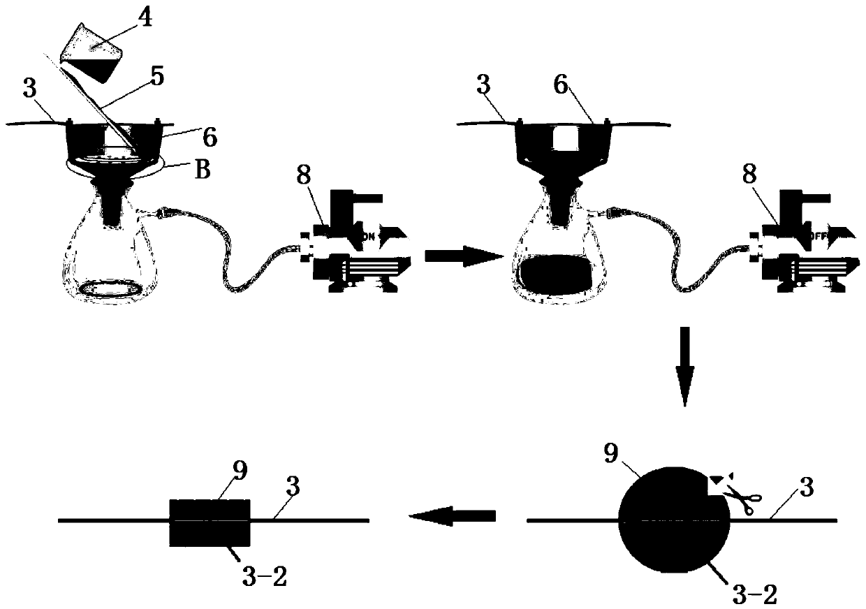
[0050] A kind of preparation method of optical fiber sensor of the present invention comprises following process:

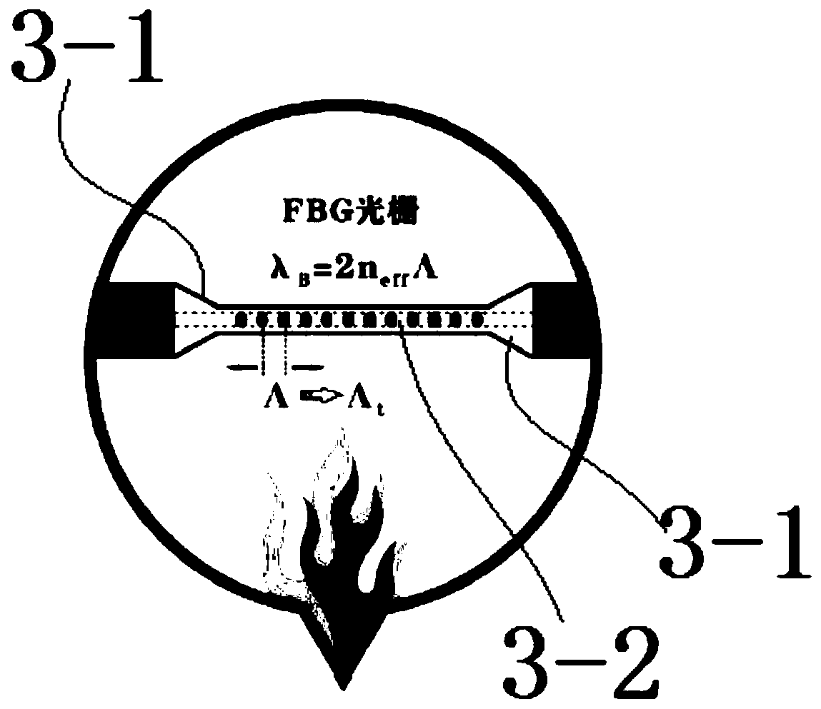
[0051] The Bragg grating is processed by the fusion tapering method to form a tapered transition zone and a waist zone with a diameter of micro-nano scale;

[0052] The graphene is coated on the waist region by using the graphene dispersion liquid and vacuum filtration, and a graphene film 10 is formed on the waist region, and the optical fiber sensor is obtained after separating the filter paper.

[0053] In the present invention, the graphene material is coated on the waist region of the single-cone interference micro-nano optical fiber sensor by a vacuum filtration preparation process, and the structural characteristics and strong adsorption capacity of graphene are used to improve the sensitivity and response characteristics of the sensor and further improve the optical fiber sensor. The sensor selectively recognizes and detects harmful gas molecules, and can...

Embodiment

[0079] What this embodiment adopts is nano-silver doped graphene to prepare optical fiber sensor, specific steps are as follows:

[0080] 1. Preparation of Ag nanoparticles doped graphene composites

[0081] specific methods:

[0082] ①Put the purchased GO powder into deionized water and disperse it ultrasonically for 1 hour to prepare a 0.5 mg / mL GO uniform dispersion. In the graphene oxide dispersion, the graphene oxide content is 0.5 mg / mL;

[0083] ②Add 35mL of dimethylacetamide aqueous solution to 35mL of the graphene oxide dispersion prepared in step ①, and magnetically stir for 1.5h; Dimethylacetamide (DMAc) and H 2 The volume ratio of O is 1:1;

[0084] ③ 3g silver nitrate (AgNO 3 ) into water to form a silver nitrate solution with a mass percentage of solute of 5%, AgNO 3 The mass ratio of content to GO in GO aqueous dispersion is 10:1, at this time, the AgNO 3 The aqueous solution was added dropwise to the above solution, and stirred for 10 min to ensure complet...


PUM

PropertyMeasurementUnit
thicknessaaaaaaaaaa
thicknessaaaaaaaaaa

Abstract

The invention discloses an optical fiber sensor and a preparation method thereof, and the method comprises the following steps: employing a fused biconical taper method to process a Bragg grating, andforming a conical transition region and a waist region with the diameter at a micro-nano scale; and coating the waist region with graphene through vacuum filtration by utilizing graphene dispersion liquid, forming a graphene film in the waist region, and separating filter paper to obtain the optical fiber sensor. According to the invention, the sensitivity and response characteristics of the sensor are improved by utilizing the structural characteristics and relatively strong adsorption capacity of graphene, the selective recognition and detection of harmful gas molecules by the optical fibersensor are improved, the measuring stability under a room temperature condition is realized, and reliable monitoring data is obtained. The preparation method is simple, the sensor is novel in structure, high in sensitivity and convenient to carry, and compared with a dispensing process, the graphene and optical fiber sensor prepared through vacuum filtration has the advantages that the compositestructure is more compact, the self-assembly structure is optimized, the sensor is convenient to expose, the gas detection sensitivity is high, and the optical fiber mechanical property is better.

Description

technical field [0001] The invention belongs to the technical field of optical fiber sensors, and in particular relates to an optical fiber sensor and a preparation method thereof. Background technique [0002] With the continuous advancement of modern science and technology and the continuous improvement and improvement of optical fiber manufacturing technology, various optical fibers with special structures and functions have been developed rapidly. Fiber optic gas sensors have been widely used in the field of toxic and harmful gas detection in recent years because of their advantages such as fast response, high precision, good selectivity, corrosion resistance and easy networking. Based on fiber optic sensors, no light source detection can be realized under harsh conditions, and the realization of downhole gas detection has become a hot research topic at present. [0003] Although the existing interferometric optical fiber sensor has relatively high sensitivity, its stab...

Claims


Application Information

Patent Timeline
Patent Type & Authority Applications(China)
IPC IPC(8): G01N21/45G02B6/255B82Y30/00B82Y40/00
CPCG01N21/45G02B6/2552B82Y30/00B82Y40/00G01N2021/458
Inventor 丁继军徐超陈海霞傅海威雍振李辉栋
Owner XI'AN PETROLEUM UNIVERSITY
Learn More