Permanent magnet motor comprising angle detection device
A permanent magnet motor, rotation angle detection technology, used in motors, electromechanical devices, transportation and packaging, etc., can solve the problems of coil short circuit, excessive lead reliability, risk, etc., to improve reliability and eliminate short circuit risks.
- Summary
- Abstract
- Description
- Claims
- Application Information
AI Technical Summary
Problems solved by technology
Method used
Image

Examples
no. 1 example
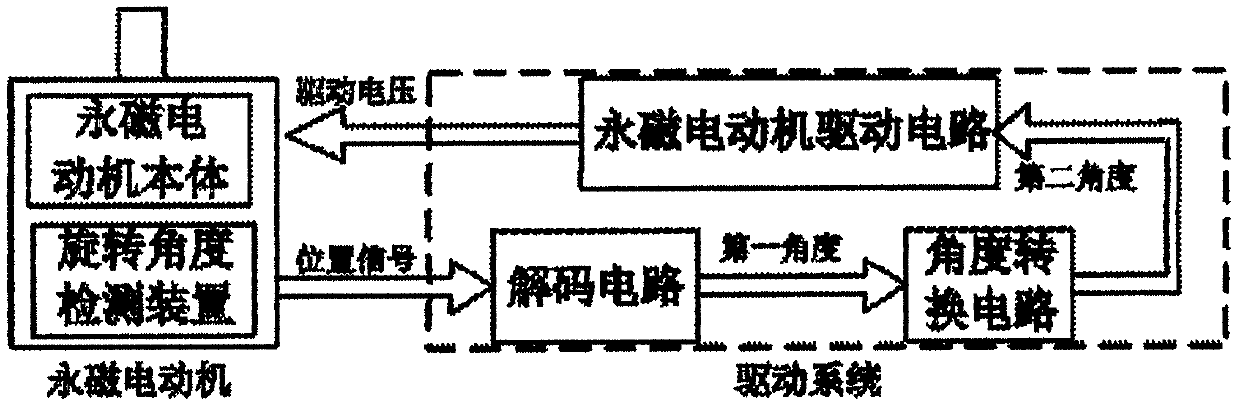
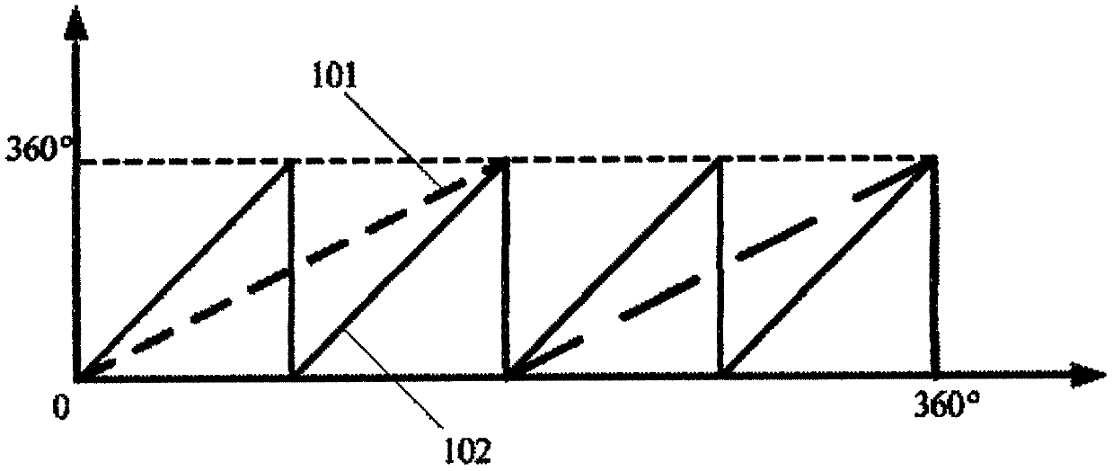
[0021] In this embodiment, take K=2, N=2, that is, in this embodiment, the permanent magnet motor body is a permanent magnet motor with a number of pole pairs of 4, the number of convex machines of the rotor of the rotation angle detection device is 2, and the permanent magnet rotor The rotor is installed on the same shaft to rotate coaxially, and the stator of the permanent magnet motor and the stator of the rotation angle detection device are installed in a common stator casing (not shown in the figure). figure 1 It is the control flowchart of the permanent magnet motor in the first embodiment of the present invention. The permanent magnet motor system is divided into two parts: the permanent magnet motor and the driving system. an angle (such as figure 2 Medium 101), figure 2 The horizontal axis corresponds to the mechanical angle that the shaft of the permanent magnet motor rotates. The angle conversion circuit multiplies the first angle by the coefficient Z (the number...
no. 2 example
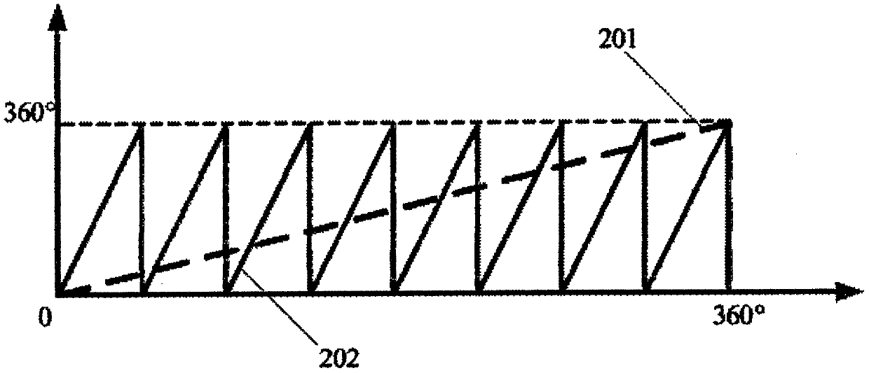
[0023] In this embodiment, get S=8, promptly in this embodiment, the permanent magnet motor body is the permanent magnet motor that the number of pole pairs is 8, and the convex machine number of the rotor of the rotation angle detecting device is 1, and the permanent magnet rotor and the rotor are installed Rotating coaxially on the same shaft, the stator of the permanent magnet motor and the stator of the rotation angle detection device are installed in a common stator casing (not shown in the figure). The control flowchart of the permanent magnet motor in the second embodiment of the present invention can also refer to figure 1 , the permanent magnet motor system is divided into two parts, the permanent magnet motor and the drive system. The position signal output by the rotation angle detection device is connected to the input terminal of the decoding circuit, and the first angle is output after decoding (such as image 3 201), image 3 The horizontal axis corresponds to ...
no. 3 example
[0025] In this embodiment, M=4, that is, in this embodiment, the permanent magnet motor body is a permanent magnet motor with a pole pair number of 4, and the number of convex machines of the rotor of the rotation angle detection device is 4, and the permanent magnet rotor and the rotor are installed Rotating coaxially on the same shaft, the stator of the permanent magnet motor and the stator of the rotation angle detection device are installed in a common stator casing (not shown in the figure). Figure 4 It is the control flow diagram of the permanent magnet motor in the third embodiment of the present invention. The permanent magnet motor system is divided into two parts: the permanent magnet motor and the driving system. An angle signal (such as Figure 5 301), Figure 5 The horizontal axis corresponds to the mechanical angle that the shaft of the permanent magnet motor rotates. The period of the first angle signal is the same as that of the rotor magnetic field of the pe...
PUM
 Abstract
Description
Claims
Application Information
 - R&D
- Intellectual Property
- Life Sciences
- Materials
- Tech Scout
- Unparalleled Data Quality
- Higher Quality Content
- 60% Fewer Hallucinations
Browse by: Latest US Patents, China's latest patents, Technical Efficacy Thesaurus, Application Domain, Technology Topic, Popular Technical Reports.
© 2025 PatSnap. All rights reserved.Legal|Privacy policy|Modern Slavery Act Transparency Statement|Sitemap|About US| Contact US: help@patsnap.com