Machining process of high-wear-resistance alloy cutter

A processing technology, alloy knife technology, applied in the field of high wear-resistant alloy knife processing technology, can solve the problems of affecting mechanical operation efficiency, economic benefits, loss of wear resistance of the tool, waste of knife body materials, etc., to reduce replacement and avoid Downtime maintenance, the effect of improving utilization

Pending Publication Date: 2020-06-12
DONGE LIYUAN MACHINERY KNIFE
View PDF10 Cites 0 Cited by
  • Summary
  • Abstract
  • Description
  • Claims
  • Application Information

AI Technical Summary

Problems solved by technology

The above-mentioned treatment method has certain sharpness and increased wear resistance on the surface after treatment, but its existing problem is that the layer thickness of the above-mentioned surface treatment is relatively thin, generally 20-40um, and the above-mentioned surface treatment layer is distributed on the surface of the knife. Two sides, during continuous work, once the thinner coating or abrasive grain layer wears out, the tool loses its wear resistance; in addition, the above coating only solves the wear resistance of the tool surface, and the sharpness of the knife edge , does not have much effect
[0018] At present, there is no good way to solve the problem of sharpness and wear resistance of the pulverizer, especially the non-shearing pulverizer. The loss of the cutter is relatively large, which seriously affects the efficiency of mechanical operation and economic benefits. also a huge waste

Method used


Image

  • Machining process of high-wear-resistance alloy cutter
  • Machining process of high-wear-resistance alloy cutter
  • Machining process of high-wear-resistance alloy cutter

Examples


Embodiment Construction

[0040] Below in conjunction with embodiment, further illustrate the present invention.

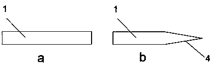
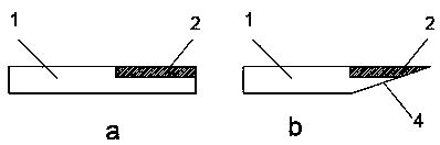
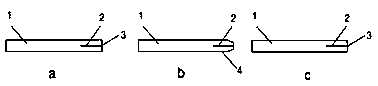
[0041] see figure 1 It can be seen that the cutter body 1 of the prior art does not have the alloy layer 2, and the blade surface of the cutter body 1 is sprayed with wear-resistant materials, and the wear-resistant abrasive grain layer is brazed to improve the wear resistance of the cutter.

[0042] After the surface treatment of the surface blade, the surface has a certain sharpness and increased wear resistance, but the problem is that the layer thickness of the above surface treatment is relatively thin, generally 20-40um, and the above surface treatment layer is distributed on both sides of the knife. One side, during continuous work, once the thinner coating or abrasive grain layer wears out, the tool loses its wear resistance; in addition, the above-mentioned coating only solves the wear resistance of the tool surface and affects the sharpness of the knife body 1 edge. , does not h...


PUM

PropertyMeasurementUnit
diameteraaaaaaaaaa
depthaaaaaaaaaa

Abstract

The invention discloses a machining process of a high-wear-resistance alloy cutter. The machining process comprises the following steps that (1), the requirements of different cutters, including the thickness of a cutter body and the thickness of a blade peak of the cutter body during normal work are determined so as to prepare the cutter body and an alloy strip with corresponding thicknesses; (2), the cutter body is machined, specifically, a strip-shaped groove is formed in the side, facing the blade peak, of one side of a blade part of the cutter body in the length direction of the cutter body, and two cutter body base layers capable of clamping an alloy layer are formed on the blade part of the cutter body; (3), the alloy strip in the strip-shaped groove is brazed to form the alloy layer, so that the blade part forms a layered structure which is formed by tightly and firmly connecting the alloy strip clamped by the two cutter body base layers; and (4), shaping and trimming the cutter body base layers are carried out to enable the side edges of the alloy strip to protrude out of the two cutter body base layers to form blade peaks and enable the cutter body base layers on the twosides of the alloy strip to form smooth blade parts. By utilizing the process to machine the alloy cutter, the steps are simpler and easy to implement, the machined alloy cutter is sharp in blade, good in abrasion resistance, long in service life and high in production efficiency in the using process, and the mechanical energy consumption is effectively reduced.

Description

technical field [0001] The invention relates to agricultural knives, in particular to a processing technology of high wear-resistant alloy knives. Background technique [0002] Grass cutters, stubble cutters, soybean milk machine blades, wheat and corn crushing knives and other knives are important parts of related equipment. During the working process, the knives are always in a state of friction with the cutting part of the straw. The high temperature and continuous friction make the blade part The loss is intensified, and the blade passivation is serious. The knife is a high-wear part of the main agricultural crushing machinery. [0003] The performance of the crushing knife is mainly reflected in two aspects: one is the sharpness of the blade; the other is the wear resistance of the blade. Moreover, the wear resistance of the blade will affect the sharpness of the blade. If the wear resistance is poor, the blade will be worn and blunt, thus losing sharpness. After the b...

Claims


Application Information

Patent Timeline
Patent Type & Authority Applications(China)
IPC IPC(8): B23P15/28
CPCB23P15/28
Inventor 许纪刚
Owner DONGE LIYUAN MACHINERY KNIFE
Why Eureka
Try Eureka