

Plasma reaction device and method for decomposing hydrogen sulfide
A reaction device and plasma technology, applied in the field of plasma chemistry, can solve the problems of low conversion rate of hydrogen sulfide, inability to achieve large flow rate, high energy consumption, etc.
- Summary
- Abstract
- Description
- Claims
- Application Information
AI Technical Summary
Problems solved by technology
Method used
Image

Examples
Embodiment 1
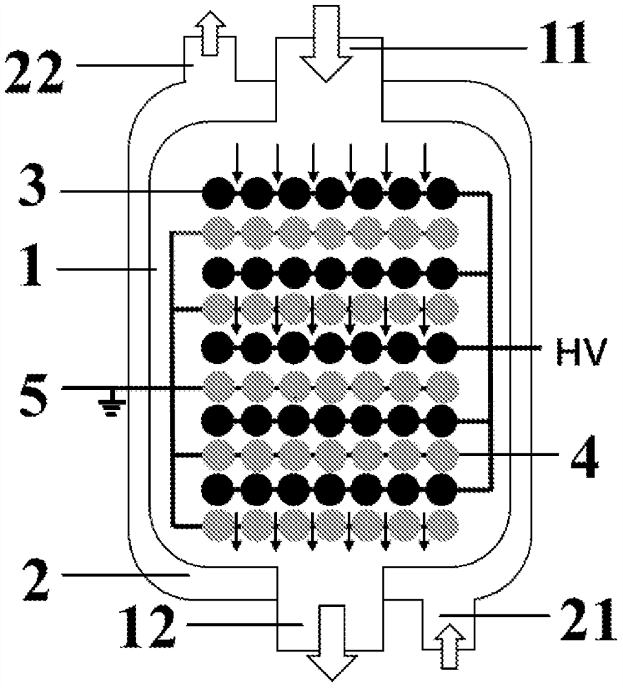
[0154] use Figure 1a The shown low-temperature plasma reaction device performs hydrogen sulfide decomposition reaction, and the specific structure and structural parameters of the low-temperature plasma reaction device are as follows:
[0155] The reaction unit includes:
[0156] a first cavity, the first cavity is respectively provided with a first inlet and a first outlet;
[0157] The second cavity, the second cavity is nested outside the first cavity, and the second cavity is respectively provided with a second inlet and a second outlet, and the The heat conduction medium can surround the outer periphery of the first cavity, and the heat conduction medium can be led out from the second outlet;
[0158]A high-voltage electrode, the high-voltage electrode is arranged in the first cavity, and the high-voltage electrode is provided with 5 layers in the first cavity; in each layer structure containing the high-voltage electrode, the high-voltage electrode The number is 7, ea...
Embodiment 2
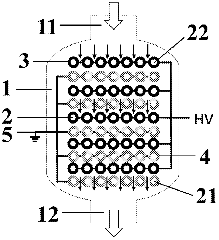
[0171] This embodiment adopts figure 2 The shown low-temperature plasma reaction device performs hydrogen sulfide decomposition reaction, and the specific structure and structural parameters of the low-temperature plasma reaction device are as follows:
[0172] The reaction unit includes:
[0173] a first cavity, the first cavity is respectively provided with a first inlet and a first outlet;
[0174] The second cavity, the second cavity is nested outside the first cavity, and the second cavity is respectively provided with a second inlet and a second outlet, and the The heat conduction medium can surround the outer periphery of the first cavity, and the heat conduction medium can be led out from the second outlet;
[0175] A high-voltage electrode, the high-voltage electrode is arranged in the first cavity, and the high-voltage electrode is provided with 5 layers in the first cavity; in each layer structure containing the high-voltage electrode, the high-voltage electrode ...
Embodiment 3
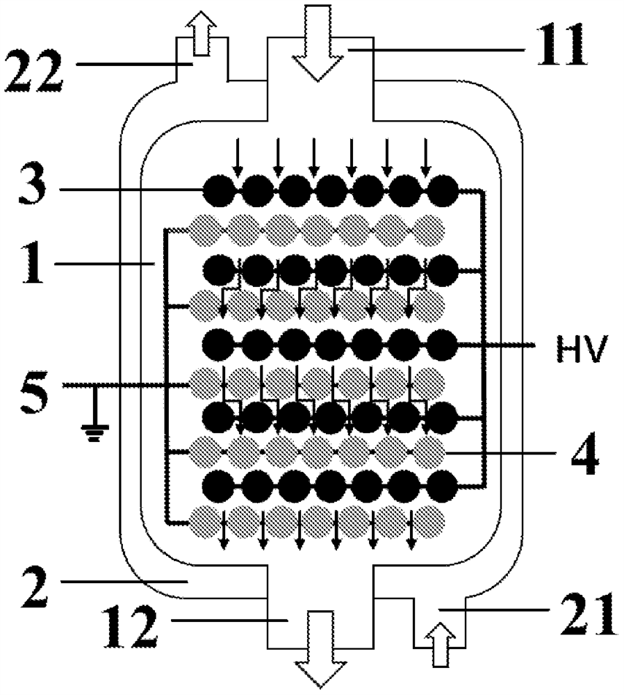
[0188] This example is carried out using a reaction device similar to that of Example 1. The difference is that the barrier medium in the reaction device of this embodiment is arranged on the outer surface of the high-voltage electrode and the ground electrode, that is, a double dielectric barrier discharge.
[0189] And the gap between two adjacent high-voltage electrodes and the two adjacent ground electrodes is equal, and the gap between two adjacent layer structures is 1.2 times the gap between two adjacent high-voltage electrodes, L 2 The ratio to the thickness D1 of the barrier medium is 15:1;
[0190] The size of each of the high-voltage electrodes is the same as that of each of the ground electrodes, and the ratio of diameter to length is 1:130;
[0191] L 2 and the length of the discharge tube L 3 The ratio between them is 1:300;
[0192] The volume of the first cavity of the low temperature plasma reaction device in this embodiment is 5.8L.
[0193] Pass H into ...
PUM
 Abstract
Description
Claims
Application Information