Automatic core discharging device for electro-spark wire-electrode cutting peripheral hole slot of tubular part

An EDM line and automatic discharge technology, which is applied in the direction of auxiliary devices, electric processing equipment, metal processing equipment, etc., can solve the problems of increasing the workload of workers, the inability to automate processing, and reducing productivity, so as to shorten the pause time and ensure continuous operation. , the effect of liberating the labor force

Pending Publication Date: 2020-06-16
SANGUANG ELECTRIC WORKING SUZHOU
View PDF0 Cites 0 Cited by
  • Summary
  • Abstract
  • Description
  • Claims
  • Application Information

AI Technical Summary

Problems solved by technology

[0006] The present invention provides an automatic core-discharging device for wire electric discharge cutting circumferential holes of tubular parts. During core processing, it is necessary to stop or suspend production and then manually or use equipment to take out the material core, resulting in problems such as the inability to automate processing, reduce productivity, increase worker workload, etc., to realize the circumferential hole cutting of tubular parts Automatic discharge of the material core during the groove to ensure the automatic and continuous operation of the machine tool

Method used


Image

  • Automatic core discharging device for electro-spark wire-electrode cutting peripheral hole slot of tubular part
  • Automatic core discharging device for electro-spark wire-electrode cutting peripheral hole slot of tubular part
  • Automatic core discharging device for electro-spark wire-electrode cutting peripheral hole slot of tubular part

Examples


Embodiment Construction

[0040] The present invention will be further described below in conjunction with accompanying drawing and embodiment:

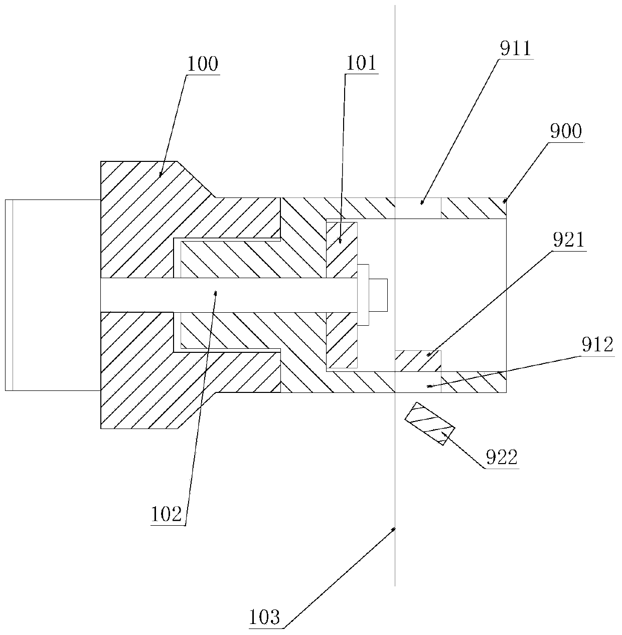
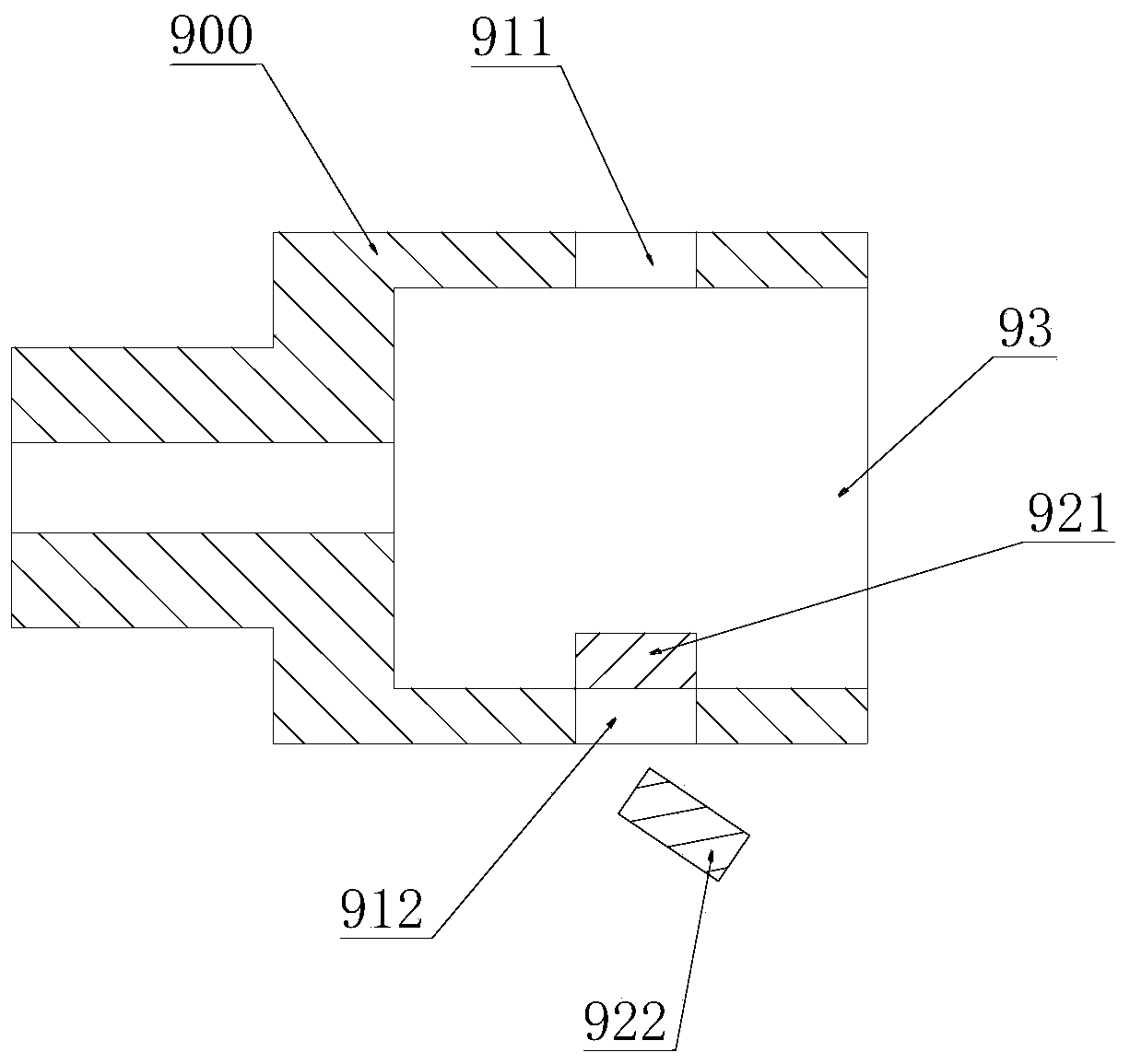
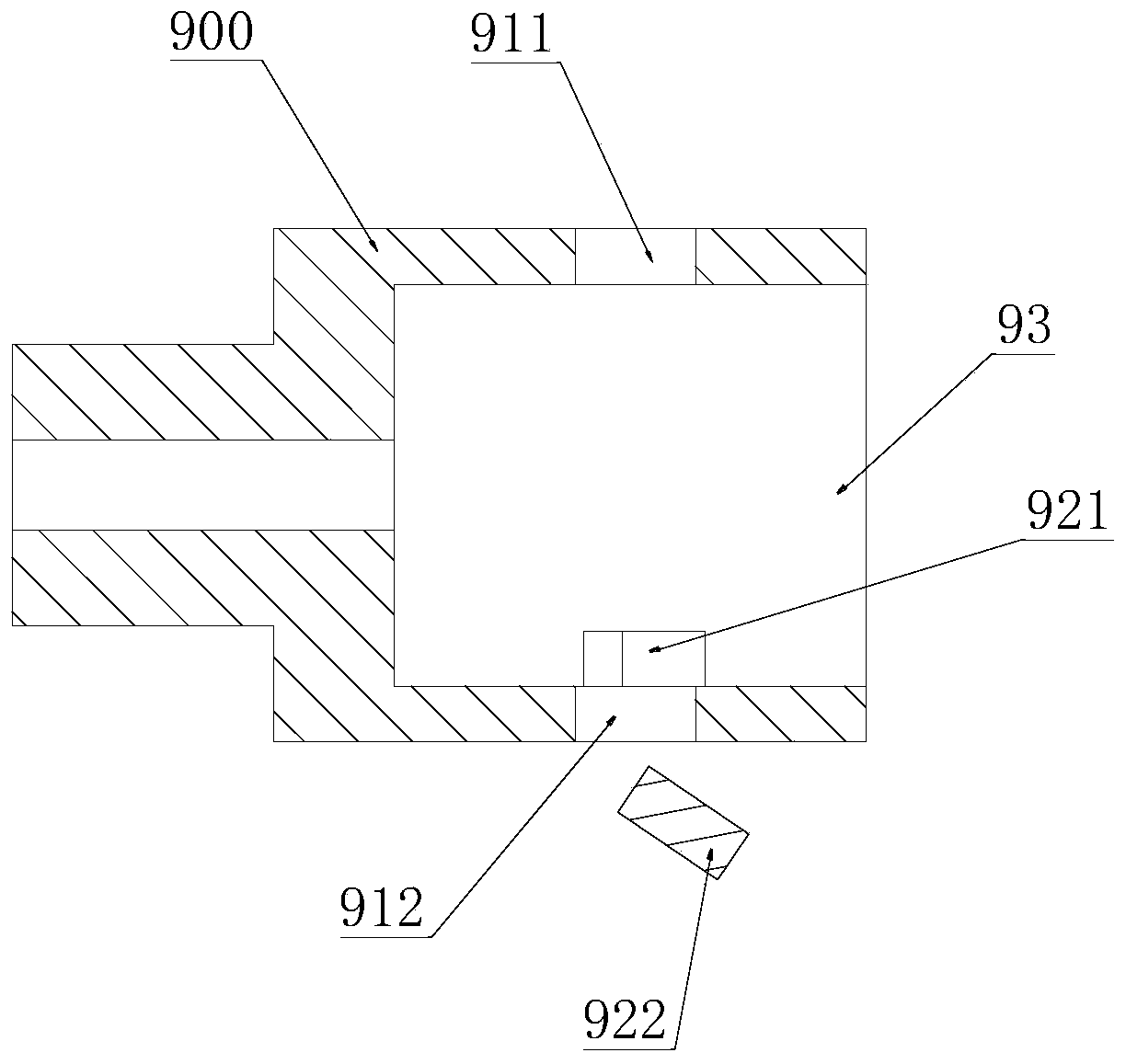
[0041] figure 2 , image 3 It is a schematic diagram showing the falling position of the feeding core 921 of a tubular part 900 in the embodiment of the present invention after one cutting, and the feeding core 921 formed in the upper hole groove 911 above the tubular part 900 will fall to the inside of the tubular part 900 and will stay near the lower hole 912 below, and the lower core 922 formed by the lower hole 912 below will fall to the outside of the tubular part 900. This upper and lower core 921, 922 is a block structure, Figure 4 is a schematic diagram of the deflection of the loading core 921 when it falls or is discharged, because the position of the loading core 921 will be deflected when it falls, so figure 2 , image 3 The drop locations in are for illustration only. It should be noted that the structure of the tubular part 900 in the pr...


PUM


Abstract

The invention discloses an automatic core discharging device for an electro-spark wire-electrode cutting peripheral hole slot of a tubular part. The automatic core discharging device comprises a clamping mechanism and a clamp main body, wherein a jet-flow channel is arranged inside the clamp main body; a jet-flow spray nozzle is arranged in the jet-flow channel; the jet-flow spray nozzle is positioned behind a lower hole slot and is adjacent to the inner hole wall of the tubular part; the jet-flow channel is provided with at least one first connecting channel in an outward extending mode; thejet-flow channel is provided with an external fluid jet-flow connector which comprises a second connecting nozzle, a fluid conveying pipeline and a feed-in mechanism. According to the scheme adopted by the invention, the jet-flow channel which extends towards the inner part and the jet-flow spray nozzle are arranged on the clamp main body, so that blocky material cores can be automatically discharged, and therefore, a discharge process is smoother and quicker to prevent material core retention from affecting follow-up wire cutting; the feed-in mechanism is used for driving the second connecting nozzle in the fluid jet-flow connector and the first connecting nozzle to automatically separate and combine so that automatic continuous operation of an electro-spark wire-electrode cutting machinetool and material core discharge is guaranteed, and automatic production needs are met.

Description

technical field [0001] The invention relates to the technical field of electric discharge wire cutting machine tools, in particular to an automatic discharge device for material cores used in the processing of circumferential hole grooves in the wire electric discharge cutting of tubular parts. Background technique [0002] The wire electric discharge cutting device (machine tool) uses the principle of electric discharge machining, uses metal wire as the processing electrode tool, and applies a pulse power supply between the workpiece and the electrode wire (copper wire, molybdenum wire) to utilize the power generated between the electrode wire and the workpiece. The workpiece is corroded by spark discharge, and at the same time, the workpiece and the electrode move according to the required shape to cut a certain shape of the workpiece. In order to achieve relatively high cutting accuracy and surface quality, often this kind of machine tool is Multiple cuts are required for...

Claims


Application Information

Patent Timeline
Patent Type & Authority Applications(China)
IPC IPC(8): B23H7/02B23H9/00B23H11/00
CPCB23H7/02B23H9/00B23H11/00
Inventor 叶军李杰周志凯
Owner SANGUANG ELECTRIC WORKING SUZHOU
Why Eureka
Try Eureka