
Optical signal transmitting device

A technology for transmitting devices and optical signals, which is applied to laser components, lasers, phonon exciters, etc., can solve the problems of increasing the length of signal lines, increasing the difficulty and cost of production brackets, and reducing parasitic inductance and parasitic capacitance. The structure is simple and the effect of reducing the installation process

Pending Publication Date: 2020-06-16
成都英思嘉半导体技术有限公司
View PDF1 Cites 3 Cited by
  • Summary
  • Abstract
  • Description
  • Claims
  • Application Information

AI Technical Summary

Problems solved by technology

But it is not difficult to see that the laser diode is perpendicular to the upper surface of the tube base through the bracket. Although the light can be output vertically along the optical path, it is still necessary to use conductive pads and transfer pads to realize the connection between the laser diode and the laser tube driver chip, increasing The length of the signal line is increased, and the bracket used is a special-shaped structure, which increases the difficulty and cost of producing the bracket

Method used


Image

  • Optical signal transmitting device
  • Optical signal transmitting device
  • Optical signal transmitting device

Examples


Embodiment 1

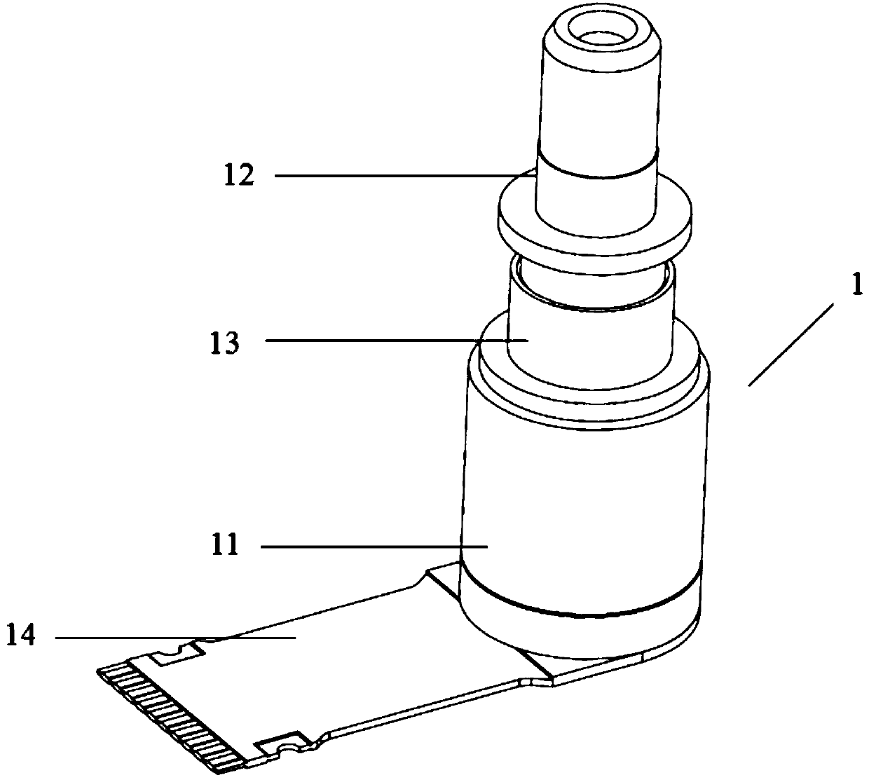
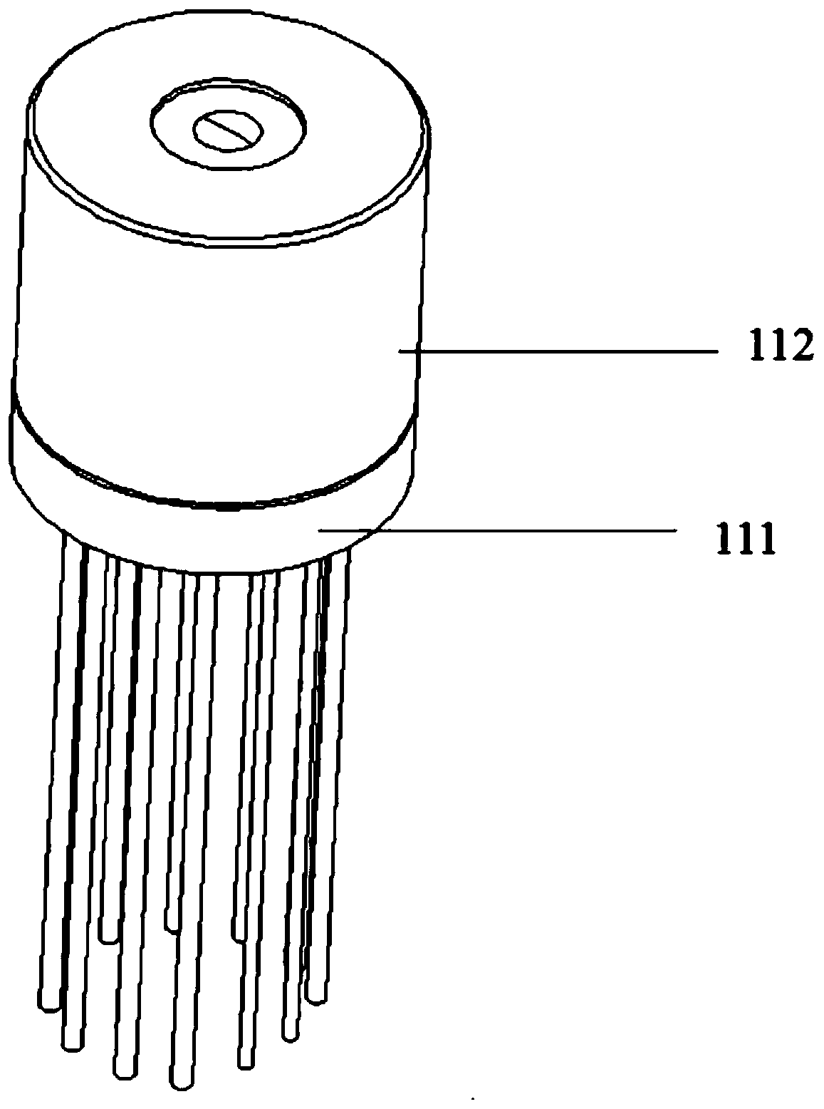
[0048] The light emitting device (1) provided by the present invention mainly includes 4 components, TO-CAN11, Receptacle12, Z-ring13 and flexible circuit board FPC14. The appearance of a light emitting device is as follows figure 1 shown. Among them, TO-CAN11 is used for packaging electronic components and optical devices; Receptacle12 is used for docking with external optical fiber connector 2; Z-ring13 is used for coupling welding between Receptacle12 and TO-CAN11; FPC14 is used for connecting the main board of optical transceiver module 3 31.

[0049] The use mode of the light emitting device 1 is placed in the optical transceiver module 3 for the emission of optical signals. figure 2 shown. One end of the Receptacle 12 is connected to the external optical fiber connector 2 , and one end of the FPC 14 is welded on the main board 31 to receive input signals and control voltages.

[0050] The structural main body of the TO-CAN component 11 of the light-emitting device 1 ...


PUM


Abstract

The invention discloses an optical signal transmitting device in the field of laser diodes. The optical signal transmitting device comprises a driving chip assembly, a laser TEC assembly and a housing, wherein the driving chip assembly and the laser TEC assembly are packaged in the housing; and a laser heat sink substrate in the laser TEC assembly comprises a first part used for installing a laserdiode chip and a second part used for installing a prism, wherein the first part is provided with a plating layer used for installing a semiconductor laser LD, and the laser heat sink substrate is further provided with a positioning structure used for positioning the prism. The device has the following beneficial effects: long wiring between the driving chip and the semiconductor laser is avoided, and the parasitic inductance and parasitic capacitance caused by long wiring are reduced, so that the problem that the parasitic inductance, parasitic capacitance, impedance mismatching and the likeinfluence the quality of high-frequency signals is solved, the use bandwidth of the optical signal transmitting device is improved, and the optical signal transmitting device is more suitable for high-speed light communication equipment.

Description

technical field [0001] The invention relates to the field of laser diodes, in particular to an optical signal emitting device. Background technique [0002] At present, the optical signal transmitting device (TOSA) and the driver chip (Driver) of the semiconductor laser (LD) commonly used in the optical transceiver module for high-speed optical fiber communication are arranged on the main board of the optical transceiver module. The driver chip (Driver) is connected to the light-emitting device (TOSA) through the flexible circuit board (FPC), and drives the semiconductor laser (LD) in the light-emitting device (TOSA). The main function of the driver chip (Driver) is to couple the DC bias current of the semiconductor laser (LD) with the high-frequency modulation current, and provide the modulated driving current for the semiconductor laser (LD). At the same time, the driver chip (Driver) can also amplify the input signal, and control the DC bias current and high-frequency mo...

Claims


Application Information

Patent Timeline
IPC IPC(8): H01S5/022H01S5/024
CPCH01S5/02415H01S5/02326H01S5/02345
Inventor 维卡斯·马南赖人铭
Owner 成都英思嘉半导体技术有限公司
Learn More