
A microwave ion propulsion device based on side wall tangent magnetic field

A technology that can cut magnetic fields and microwave ions, which is applied in the field of microwave ion propulsion devices, and can solve the problems of ionization loss on the sidewall surface, the lower thrust limit cannot meet the requirements of the lower thrust limit, and the ionization sufficiency thruster efficiency improvement is limited.

Active Publication Date: 2021-03-30
HARBIN INST OF TECH
View PDF4 Cites 0 Cited by
  • Summary
  • Abstract
  • Description
  • Claims
  • Application Information

AI Technical Summary

Problems solved by technology

In view of the low-thrust and wide-range requirements of the thruster proposed by space-based gravitational wave detection, the current ECRIT structure has the following two problems: (1) Restricted by the magnetic field conditions, the bottom wall of the ionization chamber channel will cut the diameter of the magnetic ring It cannot be too small, so that the diameter of the thruster remains high at 20 mm, and the thrust is positively correlated with the cross-section of the thruster channel, so that the lower limit of thrust that can be achieved by this type of thruster is far from meeting the requirements of the lower limit of thrust; (2) The magnetic field configuration strategy , the magnetic mirror effect can only be formed on the bottom wall of the thruster channel, and the side wall is basically unrestricted, resulting in severe ionization loss on the side wall of the entire discharge chamber, unable to maintain work in an extremely thin state of plasma, further limiting the lower limit of thrust
In addition, there are two other deficiencies that need to be improved: (1) The double magnetic ring on the bottom wall can only build two magnetic mirror areas, resulting in a single movement path for electrons between the magnetic mirror areas, and the electron movement distance is limited , ionization adequacy and booster efficiency are limited; (2) The resonance surface can only be designed on the inside of the ionization chamber outside the magnetic ring, and the design configuration is single, and the adjustable margin is small

Method used


Image

  • A microwave ion propulsion device based on side wall tangent magnetic field
  • A microwave ion propulsion device based on side wall tangent magnetic field

Examples


Embodiment Construction

[0026] It should be noted that, in the case of no conflict, the embodiments of the present invention and the features in the embodiments can be combined with each other.

[0027] The present invention will be described in detail below with reference to the accompanying drawings and examples.

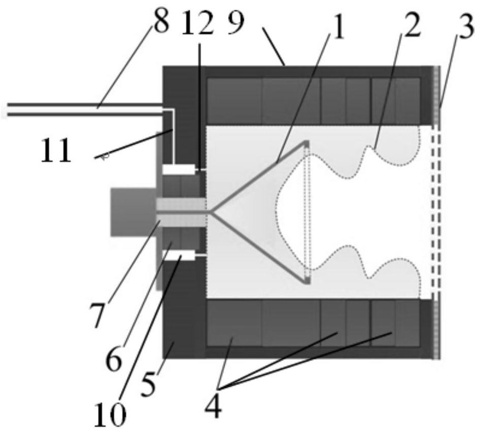
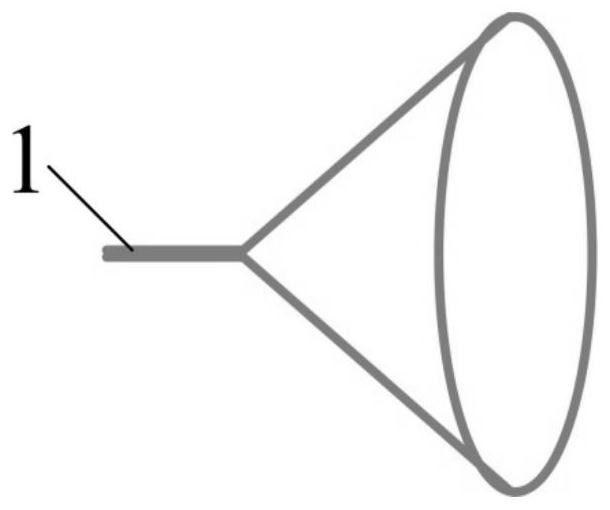
[0028] Such as Figure 1-Figure 2 As shown, a microwave ion propulsion device based on a side wall cusp magnetic field includes a discharge chamber, a side wall cusp magnetic field unit, a microwave input unit 7 and a gas supply unit. The discharge chamber includes a discharge cavity 9 and is fixed on The bottom wall 5 at the front end of the discharge chamber and the grid acceleration unit 3 fixed at the rear end of the discharge chamber, the discharge chamber 9 is a cylindrical structure, and the gas supply unit and the microwave input unit are arranged on the bottom wall 5 7. The side wall tangent magnetic field unit includes at least two side wall magnet rings 4, all side wall magne...


PUM


Abstract

The invention provides a microwave ion propelling device based on a side wall cusped magnetic field. The device comprises a discharge chamber, a side wall cusped magnetic field unit, a microwave inputunit and a gas supply unit; the discharge chamber comprises a discharge cavity, a bottom wall and a grid acceleration unit, and the gas supply unit and the microwave input unit are arranged on the bottom wall; the side wall cusped magnetic field unit at least comprises two side wall magnet rings, all the side wall magnet rings and the discharge cavity are coaxially arranged, all the side wall magnet rings are arranged on the inner wall face of the discharge cavity in a homopolar opposite mode, the multiple side wall magnet rings are fully distributed on the inner wall face of the discharge cavity, and the side wall cusped magnetic field unit forms an electron cyclotron resonance surface in the discharge chamber; the microwave input unit extends into the center of the bottom wall of the discharge chamber to input microwaves for the hollow cone-cage antenna, and the hollow cone-cage antenna is located in a high-intensity magnetic field area on the upstream of the electron cyclotron resonance surface; and the gas supply unit introduces working medium gas into the discharge cavity. According to the device, lower plasma density and lower thrust lower limit can be maintained.

Description

technical field [0001] The invention belongs to the field of plasma micro-propulsion, in particular to a microwave ion propulsion device based on a side wall tangent magnetic field. Background technique [0002] With the demand for space-based gravitational wave detection missions in recent years, the satellite spacing accuracy of the satellite formation is required to reach 10-21. ), high precision, high stability and high resolution (0.1μN) thrust requirements, which in turn require the miniaturization of the propulsion device. [0003] Electron Cyclotron Resonance Ion Thruster (ECRIT) is a thruster that uses microwave frequency to resonate with the frequency of electrons orbiting magnetic lines of force, and then heats electrons to generate working fluid ionization, and then uses the ion beam ejected at high speed by the grid electric field to generate reaction force. It has the characteristics of high ionization rate, high specific impulse and simple structure. Japan's...

Claims


Application Information

Patent Timeline
Patent Type & Authority Patents(China)
IPC IPC(8): F03H1/00
CPCF03H1/0012F03H1/0018F03H1/0031F03H1/0093
Inventor 朱悉铭孟圣峰梁崇王彦飞于达仁宁中喜
Owner HARBIN INST OF TECH
Learn More