
Temperature Compensation Device of Reinforced Fiber Composite Fiber Bragg Grating Strain Sensor

A technology of temperature compensation device and strain sensor, which is applied to thermometers with physical/chemical changes, optical devices, thermometers, etc., can solve problems such as low temperature compensation accuracy and center wavelength drift difference, and achieve temperature compensation. Waterproof and sealing performance, the effect of improving the survival rate

Active Publication Date: 2021-03-09
CHINA SHIP SCIENTIFIC RESEARCH CENTER (THE 702 INSTITUTE OF CHINA SHIPBUILDING INDUSTRY CORPORATION)
View PDF15 Cites 0 Cited by
  • Summary
  • Abstract
  • Description
  • Claims
  • Application Information

AI Technical Summary

Problems solved by technology

[0004] Due to the different monitoring positions of the hull, in order to achieve the best strain measurement effect, the fiber grating strain measurement sensor is embedded in different layup positions, and the thermal strain characteristics of different glass fiber cloth layups in the glass fiber sandwich structure are obviously different. The traditional method uses a temperature-compensated optical fiber at a layer position to perform temperature compensation on the strain measurement optical fiber at a different layer position, resulting in a significant difference in the central wavelength drift between the fiber grating strain measurement sensor and the temperature compensation sensor, resulting in low temperature compensation accuracy

Method used


Image

  • Temperature Compensation Device of Reinforced Fiber Composite Fiber Bragg Grating Strain Sensor
  • Temperature Compensation Device of Reinforced Fiber Composite Fiber Bragg Grating Strain Sensor
  • Temperature Compensation Device of Reinforced Fiber Composite Fiber Bragg Grating Strain Sensor

Examples


Embodiment Construction

[0031] The specific implementation manner of the present invention will be described below in conjunction with the accompanying drawings.

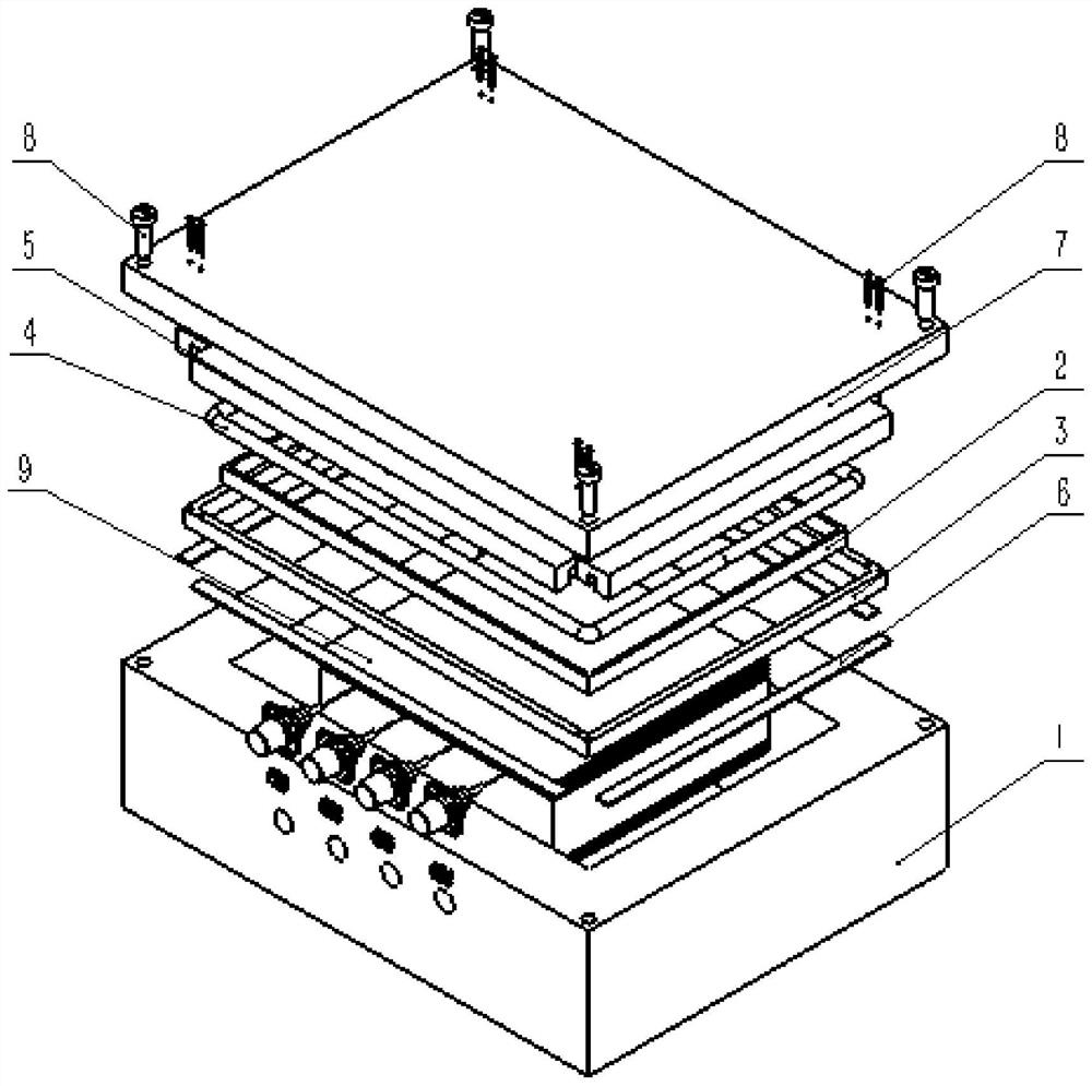
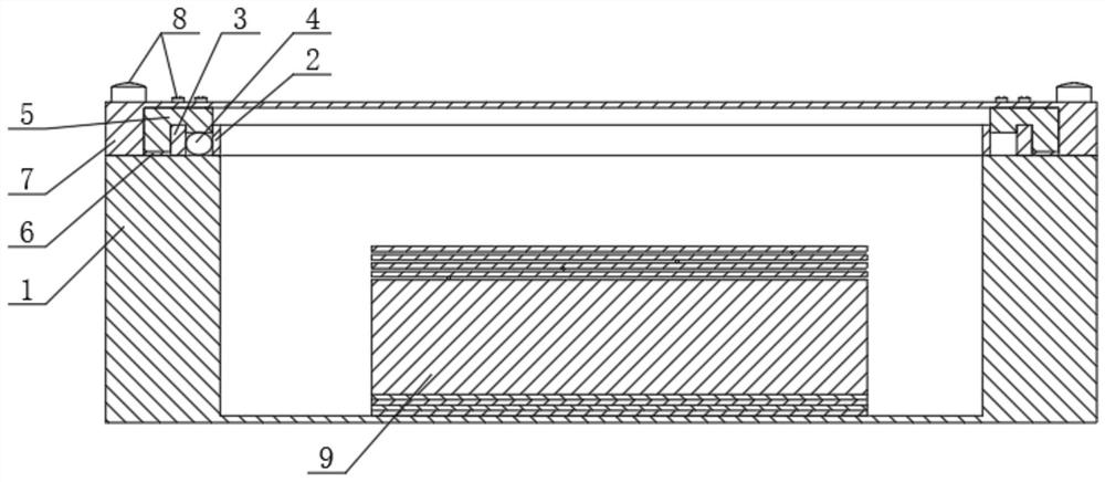
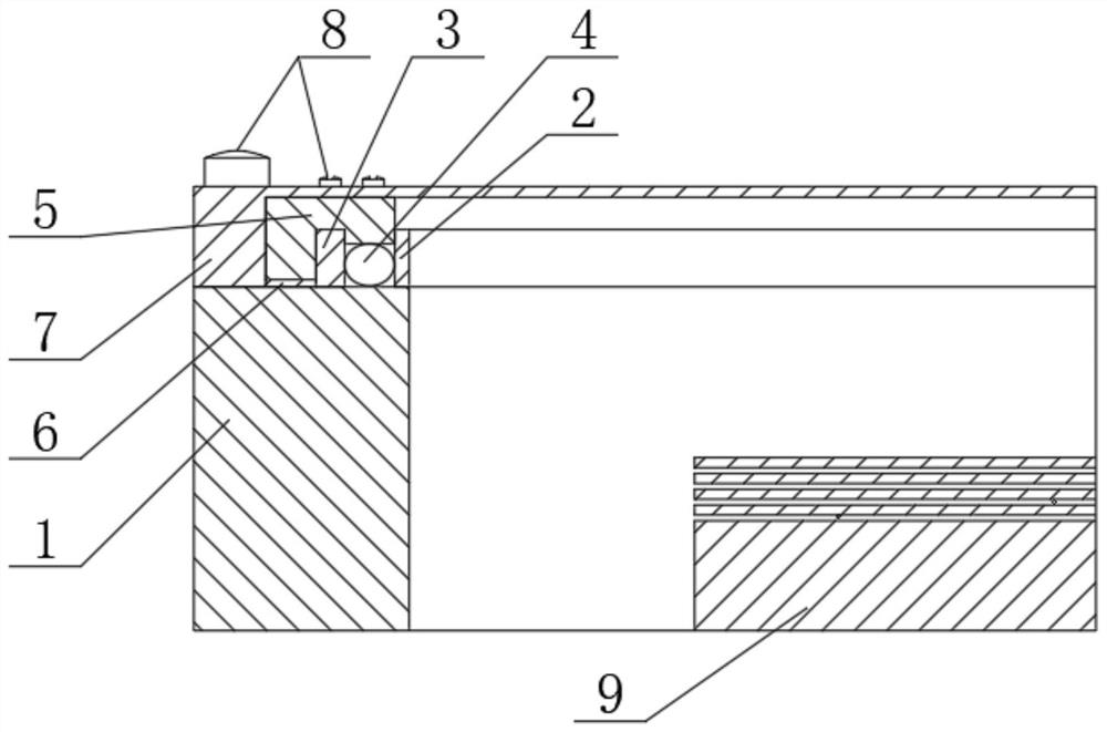
[0032] Such as Figure 1-Figure 3 As shown, the temperature compensation device of the reinforced fiber composite material fiber grating strain sensor of this embodiment includes a base 1, the base 1 is a box structure with an open top, and a fiber grating temperature compensation device 9 is installed inside it, and the box structure opening The inner ring of the end face at the center is provided with an inner positioning ring 2, and its outer ring is provided with an outer positioning ring 3, and a sealing ring 4 is installed in the gap formed between the inner positioning ring 2 and the outer positioning ring 3, and the sealing ring 4 and the outer positioning ring 3. A pre-tightening block 5 is arranged above the pre-tightening block 5. A groove matching the outer positioning ring 3 is arranged on the pre-tightening pressing block 5. ...


PUM


Abstract

The invention relates to a temperature compensation device for a fiber grating strain sensor of reinforced fiber composite material, which comprises a base in which a fiber grating temperature compensation device is arranged: four layers of glass fiber cloth prepregs are respectively laid on the upper and lower ends of a foam core material, and Between the four layers of glass fiber cloth prepregs, between the foam core material and the glass fiber cloth prepregs, temperature compensating optical fibers are respectively embedded, and the three are integrated through the curing molding process. Lead out from one side, pass through the sleeve at the edge of the glass fiber cloth prepreg, and weld and connect with the jumper in the heat shrinkable sleeve. The jumper port is connected to the input port of the adapter, and the adapter passes through the mounting hole on the front side of the base. And it is connected to the base through fixing screws, thereby solving the problem of thermal strain differences at different lay-up positions of the composite material, which causes the center wavelength drift difference of the fiber grating temperature compensation sensor. The seal seals for an improved watertight seal.

Description

technical field [0001] The invention relates to the technical field of optical fiber sensing, in particular to a temperature compensation device for a fiber grating strain sensor of a reinforced fiber composite material, which is specifically applied to the structural health monitoring of a reinforced fiber composite material ship. Background technique [0002] With the continuous improvement of the application level of composite materials in the field of ships, the internal load transfer law, failure mode and long-term monitoring of structural health of hull composite materials under load have attracted widespread attention. Fiber Bragg Grating strain sensors rely on their simple structure and no electromagnetic interference , corrosion resistance, and good compatibility with the resin matrix. By embedding it inside the composite material, the method of on-line monitoring the structural stress and strain during the use of the composite material has been widely used. [0003...

Claims


Application Information

Patent Timeline
Patent Type & Authority Patents(China)
IPC IPC(8): G01K11/32G01K1/08G01B11/16G01K11/3206
CPCG01K11/3206G01K1/08G01B11/165
Inventor 韦朋余张若楠张亦龙李生鹏陈哲姜朝文周舒豪
Owner CHINA SHIP SCIENTIFIC RESEARCH CENTER (THE 702 INSTITUTE OF CHINA SHIPBUILDING INDUSTRY CORPORATION)
Learn More