Broadband high-gain microstrip antenna

A microstrip antenna, high-gain technology, applied in antennas, antenna arrays, antenna grounding devices, etc., can solve the problems that limit the wide application of ultra-wideband positioning technology, narrow antenna impedance bandwidth, and limit wide application, etc., to achieve good gain stability , Improve the antenna gain, improve the effect of omnidirectionality and stability

Pending Publication Date: 2020-06-19
苏州竺星信息科技有限公司
View PDF0 Cites 3 Cited by
  • Summary
  • Abstract
  • Description
  • Claims
  • Application Information

AI Technical Summary

Problems solved by technology

[0004] 1. Insufficient bandwidth: limited by the narrow bandwidth of the phase shifter, the impedance bandwidth of the antenna becomes very narrow after multiple phase shifters are connected in series
The impedance characteristics of the Franklin antenna limit its wide application in ultra-wideband positioning technology
[0005] 2. The omnidirectionality of the antenna pattern has defects as the working frequency deviates from the center frequency: the Franklin antenna generally adopts the form of series feeding
This pattern characteristic of the Franklin antenna also limits its wide application in ultra-wideband positioning technology

Method used


Image

  • Broadband high-gain microstrip antenna
  • Broadband high-gain microstrip antenna
  • Broadband high-gain microstrip antenna

Examples


Embodiment 1

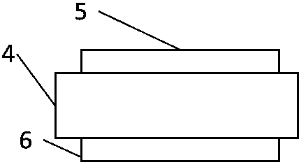
[0033] Such as figure 2 As shown, a broadband high-gain microstrip antenna has a three-layer structure, including a dielectric substrate 4 , a radiator array layer 5 and a ground plane layer 6 . The dielectric substrate layer 4 is located in the middle layer, the upper layer of the dielectric substrate 4 is the radiator array layer 5, and the lower layer of the dielectric substrate layer 4 is the grounding layer.

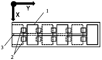
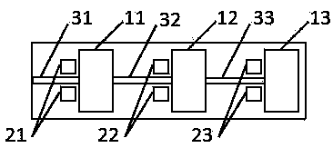
[0034] Such as image 3 As shown, the radiator array layer is composed of 3 rectangular microstrip patches 11 , 12 , 13 , 3 pairs of rectangular coupling patch pairs 21 , 22 , 23 and 50Ω feed microstrip lines 31 , 32 , 33 . A rectangular microstrip patch and a rectangular coupling patch pair respectively constitute a radiation unit, for example, a rectangular microstrip patch 11 and a rectangular coupling patch pair 21 constitute a radiation unit. The 50Ω feeding microstrip lines 31 , 32 , 33 are connected to the three rectangular microstrip patches 11 , 12 , 13 ...

Embodiment 2

[0045] Such as Figure 5 As shown, the antenna in this embodiment is composed of the broadband high-gain microstrip antenna 7 in Embodiment 1, an isolation post 8 and a reflector 9 , and the reflector 9 is behind the antenna 7 and connected by the isolation post 8 . By adjusting the length and width of the reflector 9 and the distance from the antenna 7, the reflector 9 has basically no influence on the performance of the reflection coefficient of the antenna 7, and the gain of the antenna can be further improved and the positioning distance can be extended.

[0046] In this embodiment, the size of the reflector is preferably 64*176*1.5 mm³, and the material is aluminum; the distance between the reflector and the antenna is preferably 22 mm; the reflector supports the antenna through 4 isolation columns; 4 isolation columns It is a nylon spacer, its diameter is preferably 6mm, and its height is preferably 22mm.

[0047] Figure 7 is a reflection coefficient diagram of a broa...


PUM

PropertyMeasurementUnit
widthaaaaaaaaaa
lengthaaaaaaaaaa
widthaaaaaaaaaa

Abstract

The invention discloses a broadband high-gain microstrip antenna. The broadband high-gain microstrip antenna comprises a dielectric substrate, a radiator array and a grounding plate multilayer structure, and the top layer of the dielectric substrate is a radiator array which is composed of N rectangular microstrip patches (1), N pairs of rectangular coupling patch pairs (2) and a feed microstrip line (3). The 50-ohm feed microstrip line (3) is connected with the N rectangular microstrip patches (1) and feeds the N rectangular microstrip patches (1) in series; the N pairs of rectangular coupling patch pairs (2) are symmetrically distributed on two sides of the feed microstrip line (3); the structure of the grounding plate layer is similar to that of the radiator array layer, and the grounding plate layer and the top radiation unit are arranged in a staggered manner; the specific numerical value of N is determined according to system gain and system size requirements; and the broadband high-gain microstrip antenna is wide in bandwidth, good in omnidirectivity, high in gain, small in size, compact in structure and convenient to process.

Description

technical field [0001] The invention relates to the technical field of antennas, in particular to a wide-band high-gain microstrip antenna. Background technique [0002] With the emergence of the Internet of Things, a large number of traditional industries have embarked on the road of intelligence. With the increasing demand for IoT scenarios, the demand for indoor positioning is increasing. Different levels of indoor positioning technology are required for smart prisons, smart elderly care, smart construction sites, and smart attendance. It has the advantages of strong penetrating power, low power consumption, good anti-interference ability, high security, low system complexity, and high-precision positioning. Positioning technology, infrared positioning technology) stand out and become a research hotspot. [0003] As the transmitter and receiver of information in the ultra-wideband positioning system, the antenna plays a connecting role for the entire system, so its per...

Claims


Application Information

Patent Timeline
Patent Type & Authority Applications(China)
IPC IPC(8): H01Q1/12H01Q1/38H01Q1/48H01Q1/50H01Q19/10H01Q21/00H01Q21/08
CPCH01Q1/12H01Q1/38H01Q1/48H01Q1/50H01Q19/104H01Q21/0075H01Q21/08
Inventor 何赛灵罗淼辉刘辉
Owner 苏州竺星信息科技有限公司
Why Eureka
Try Eureka