Small ultra-wideband different-plane mirror image dipole array antenna

An array antenna and dipole technology, which is applied in the field of small ultra-wideband heterogeneous mirror dipole array antennas, can solve the problems of difficult integration, low gain, large size, etc., and achieve simple production, strong consistency, and good consistency Effect

Active Publication Date: 2020-06-19
HUBEI SANJIANG SPACE XIANFENG ELECTRONICS&INFORMATION CO LTD
View PDF15 Cites 0 Cited by
  • Summary
  • Abstract
  • Description
  • Claims
  • Application Information

AI Technical Summary

Problems solved by technology

At present, domestic and foreign journals and patents have introduced ultra-wideband patch antennas, but most of them have low gain and radiation directions in the entire working frequency band. Figure 1 Problems such as poor consistency, large size, and difficulty in integrating into microwave links limit its popularization and application

Method used


Image

  • Small ultra-wideband different-plane mirror image dipole array antenna
  • Small ultra-wideband different-plane mirror image dipole array antenna
  • Small ultra-wideband different-plane mirror image dipole array antenna

Examples


Embodiment Construction

[0028] In order to make the object, technical solution and advantages of the present invention clearer, the present invention will be further described in detail below in conjunction with the accompanying drawings and embodiments. It should be understood that the specific embodiments described here are only used to explain the present invention, not to limit the present invention. In addition, the technical features involved in the various embodiments of the present invention described below can be combined with each other as long as they do not constitute a conflict with each other. The present invention will be further described in detail below in combination with specific embodiments.

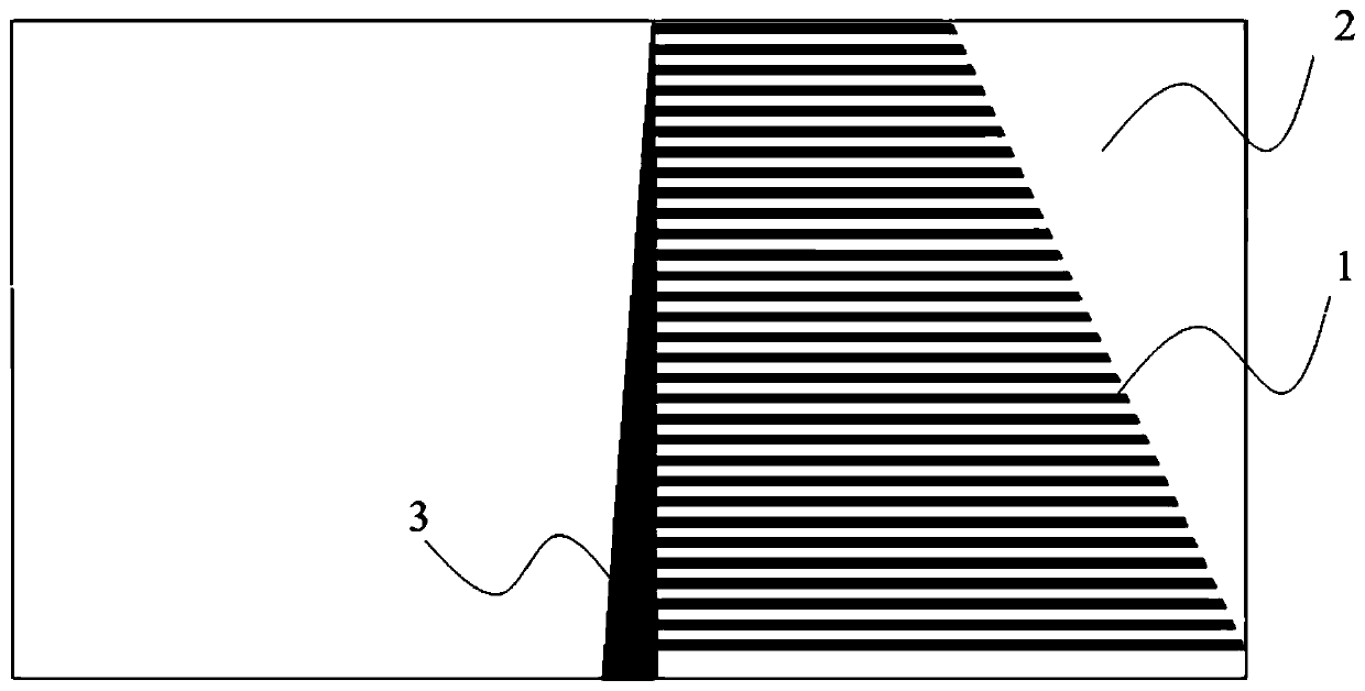
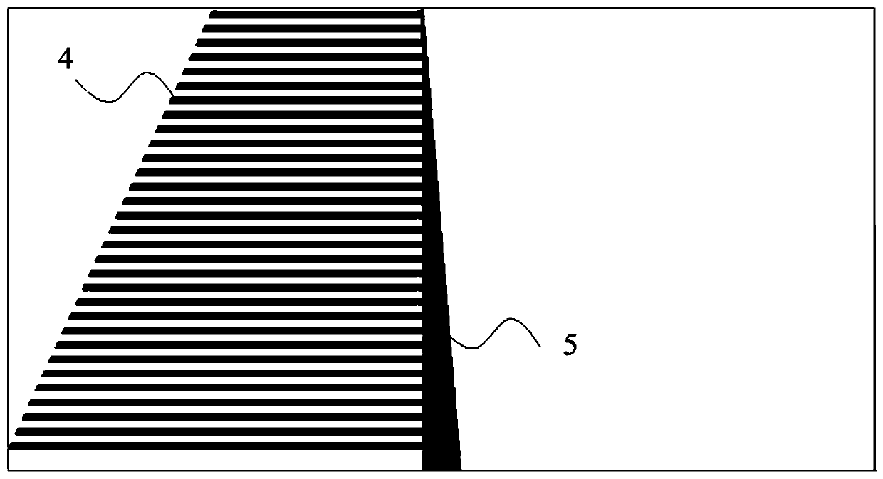
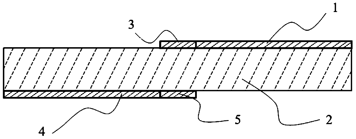
[0029] As a preferred embodiment of the present invention, such as Figure 1-3 As shown, the present invention provides a small ultra-broadband heteroplanar mirror dipole array antenna, which is characterized in that: it includes a top layer structure, an intermediate microwave dielectric m...


PUM

PropertyMeasurementUnit
thicknessaaaaaaaaaa
thicknessaaaaaaaaaa
lengthaaaaaaaaaa

Abstract

The invention discloses a small ultra-wideband different-plane mirror image dipole array antenna, which comprises a top-layer stepped comb-shaped structure printed line, a top-layer triangular printedline, a middle microwave dielectric material layer, a bottom-layer stepped comb-shaped structure printed line and a bottom-layer triangular printed line at the end part of the bottom-layer stepped comb-shaped structure printed line, wherein the top-layer triangular printed line, the middle microwave dielectric material layer and the bottom-layer stepped comb-shaped structure printed line at the end part of the top-layer stepped comb-shaped structure printed line; the top-layer stepped comb-shaped structure printed line and the bottom-layer stepped comb-shaped structure printed line are in different-surface mirror symmetry in structure to form different-surface dipoles of the array antenna; by linearly increasing or decreasing the number of dipole pairs with different arm lengths on the basis of the different-plane dipoles, the working bandwidth of the whole antenna can be adjusted, and the consistency of a radiation pattern can be kept; and the radiation pattern of the array antenna is parallel to the axial direction of the antenna. The antenna adopts a common PCB dielectric material, can be processed and manufactured more conveniently, and has the advantages of small size, adjustable frequency, good directional diagram consistency in the whole working frequency band, axial radiation direction and the like, thereby showing that the antenna has a wider application prospect.

Description

technical field [0001] The invention belongs to the field of wideband antennas in wireless communication systems, and in particular relates to a small ultra-wideband different-plane mirror dipole array antenna. Background technique [0002] With the rapid development of wireless communication technology, communication systems have gradually increased the bandwidth and frequency band requirements of antennas. In recent years, Ultm-WideBandwidth (UWB) antennas have gradually emerged with the characteristics of wide frequency bandwidth, low power spectral density, and high transmission rate. , and gradually come into people's field of vision, the array antenna involved in the ultra-wideband antenna must have a wide-band performance, and its bandwidth often reaches GHz. As a microwave device printed directly on the RF PCB, the patch antenna has a high degree of integration and is relatively convenient for debugging. It has attracted more and more attention in recent years. At p...

Claims


Application Information

Patent Timeline
Patent Type & Authority Applications(China)
IPC IPC(8): H01Q1/38H01Q1/50H01Q5/25H01Q9/16H01Q21/00
CPCH01Q1/38H01Q1/50H01Q5/25H01Q9/16H01Q21/00
Inventor 陈伟李美菊徐祥华
Owner HUBEI SANJIANG SPACE XIANFENG ELECTRONICS&INFORMATION CO LTD
Why Eureka
Try Eureka