
Friction layer material of triboelectric nanogenerator and its preparation method and application

A nano-generator, friction layer technology, applied in the direction of triboelectric generators, can solve the problems of complex operation, high cost, decreased electrical output performance, etc., and achieve the effects of simple operation, low cost, and expansion of application fields.

Active Publication Date: 2020-12-29
TIANJIN UNIVERSITY OF TECHNOLOGY
View PDF7 Cites 0 Cited by
  • Summary
  • Abstract
  • Description
  • Claims
  • Application Information

AI Technical Summary

Problems solved by technology

Another example is in the field of superhydrophobic, which is also affected by the limitations and performance of superhydrophobic materials, and there is a decline in electrical output performance when applied in a humid environment.
In addition, relevant reports have confirmed that increasing the surface roughness and applied charge of the friction layer material can also improve its electrical output performance. However, the methods of photolithography and high-voltage polarization in traditional reports are not only costly, but also complicated to operate. , and there is a certain risk

Method used


Image

  • Friction layer material of triboelectric nanogenerator and its preparation method and application
  • Friction layer material of triboelectric nanogenerator and its preparation method and application
  • Friction layer material of triboelectric nanogenerator and its preparation method and application

Examples


Embodiment 1

[0058] A method for preparing a friction layer material of a friction nanogenerator, comprising the following steps:

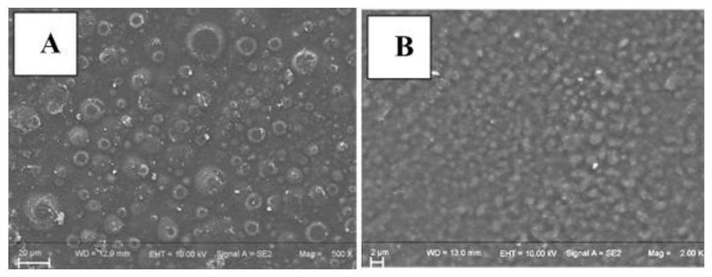
[0059] 1) The friction layer A and the friction layer B are laser etched, so that the roughness of the bottom surface of the friction layer A reaches 75%, and the roughness of the top surface of the friction layer B reaches 90%. The etched pattern is triangular and circular, the angle of the second laser etching is adjusted to 90°, the laser etching power is 5W, the laser etching speed is 500mm / s, and the line width spacing is 0.02mm. The photomicrographs of friction layer B before and after laser etching are shown in figure 2 ,in, figure 2 A is the photomicrograph before etching, figure 2 B is the photo after laser etching, and the pattern structure formed when the bubbles burst on the surface can be observed. This is the first time to increase the surface roughness of the friction layer B, and the roughness can reach about 40%. After two times of laser ...

Embodiment 2

[0065] A method for preparing a friction layer material of a friction nanogenerator, comprising the following steps:

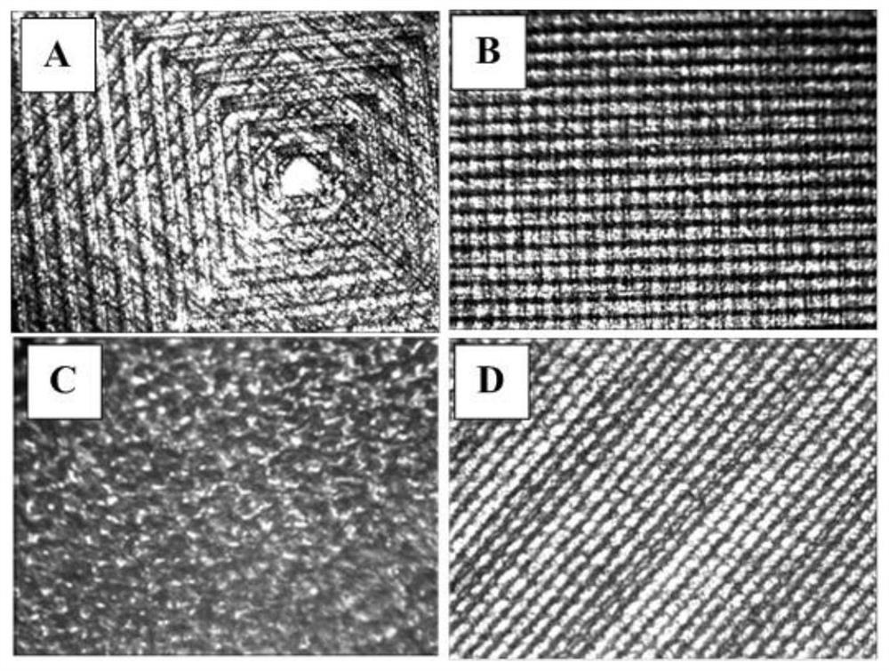
[0066] 1) Laser etching the friction layer A and the friction layer B, so that the roughness of the bottom surface of the friction layer A reaches 70%, and the roughness of the top surface of the friction layer B reaches 70%. The etched pattern is back-shaped, and the second laser etching is performed after the laser scanning angle is rotated by 45°. The laser etching power is 10W, the laser etching speed is 500mm / s, and the line width spacing is 0.05mm. Friction layer B etching micro-pattern structure see image 3 a.

[0067] 2) Put the bottom surface of the friction layer A and the top surface of the friction layer B into the plasma generator respectively for plasma treatment, the time of plasma treatment is 20min, the voltage of plasma treatment is 10KV, and the current of plasma treatment is 0.6A;

[0068] in:

[0069] Friction layer A has a thickness o...

Embodiment 3

[0072] A method for preparing a friction layer material of a friction nanogenerator, comprising the following steps:

[0073] 1) Laser etching the friction layer A and the friction layer B, so that the roughness of the bottom surface of the friction layer A reaches 90%, and the roughness of the top surface of the friction layer B reaches 85%. The pattern to be etched is linear, rotated 90° during the second laser etching, the laser etching power is 15W, the laser etching speed is 1000mm / s, and the line width spacing is 0.01mm. Friction layer B etching micro-pattern structure see image 3 b.

[0074] 2) Put the bottom surface of friction layer A and the top surface of friction layer B into the plasma generator respectively for plasma treatment, the time of plasma treatment is 15min, the voltage of plasma treatment is 10KV, and the current of plasma treatment is 0.5A;

[0075] in:

[0076] The friction layer A has a thickness of 35 μm and a size of 4×4 cm 2 , the method of p...


PUM

PropertyMeasurementUnit
thicknessaaaaaaaaaa
thicknessaaaaaaaaaa
thicknessaaaaaaaaaa

Abstract

The invention discloses a friction nano-generator friction layer material as well as a preparation method and application thereof. The preparation method comprises the steps of carrying out laser etching on a friction layer A and a friction layer B so as to enable the roughness of the bottom surface of the friction layer A to reach 30-90% and enable the roughness of the top surface of the frictionlayer B to reach 30-90%; and carrying out plasma treatment respectively on the bottom surface of the friction layer A and the top surface of the friction layer B, wherein the plasma treatment time is1-120min, the plasma treatment voltage is 5-15KV, and the plasma treatment current is 0.5-0.6A. The invention provides a preparation method of the friction nano-generator friction layer material. Thepreparation method is low in cost and simple to operate. According to the preparation method, the selection range of an easily-obtained electronic polymer material and a volatile electronic polymer material is wide, the electron obtaining / losing performance of the obtained friction nano-generator friction layer material is high, then the electric output performance of the friction nano-generatoris improved by 50%-500%, and the application field is expanded.

Description

technical field [0001] The invention belongs to the technical field of nanometer generators, and in particular relates to a friction layer material of a friction nanometer generator and its preparation method and application. Background technique [0002] In recent years, the demand for energy has been increasing, and the consumption of traditional non-renewable energy has been increasing. The ensuing energy crisis and environmental pollution have become more and more serious, which has gradually attracted widespread attention from all over the world. The search for green and sustainable energy has gradually become a research hotspot for researchers from all over the world, and the self-driven device realized by the triboelectric nanogenerator has gradually become a recognized innovative research in the world, and has a wide range of applications in the fields of biomedicine, energy, electronic communication, etc. . [0003] Relevant studies have shown that the electrical o...

Claims


Application Information

Patent Timeline
Patent Type & Authority Patents(China)
IPC IPC(8): H02N1/04C08L1/28C08L77/06C08L67/04
CPCC08L1/28C08L67/04C08L77/06H02N1/04
Inventor 李伟陈民芳赵云翟永梅
Owner TIANJIN UNIVERSITY OF TECHNOLOGY
Learn More