Boiler waste gas treatment device for environmental protection
A boiler exhaust gas and treatment device technology, which is applied in the direction of fixed tubular conduit components, dispersed particle filtration, lighting and heating equipment, etc., can solve the problems of poor treatment effect, waste of resources, waste of flue gas heat, etc., and achieve simple structure and extended Use cycle, the effect of saving heat energy resources
- Summary
- Abstract
- Description
- Claims
- Application Information
AI Technical Summary
Problems solved by technology
Method used
Image

Examples
Embodiment 1
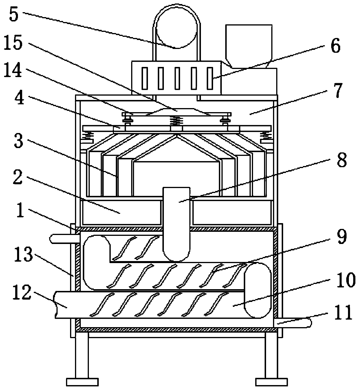
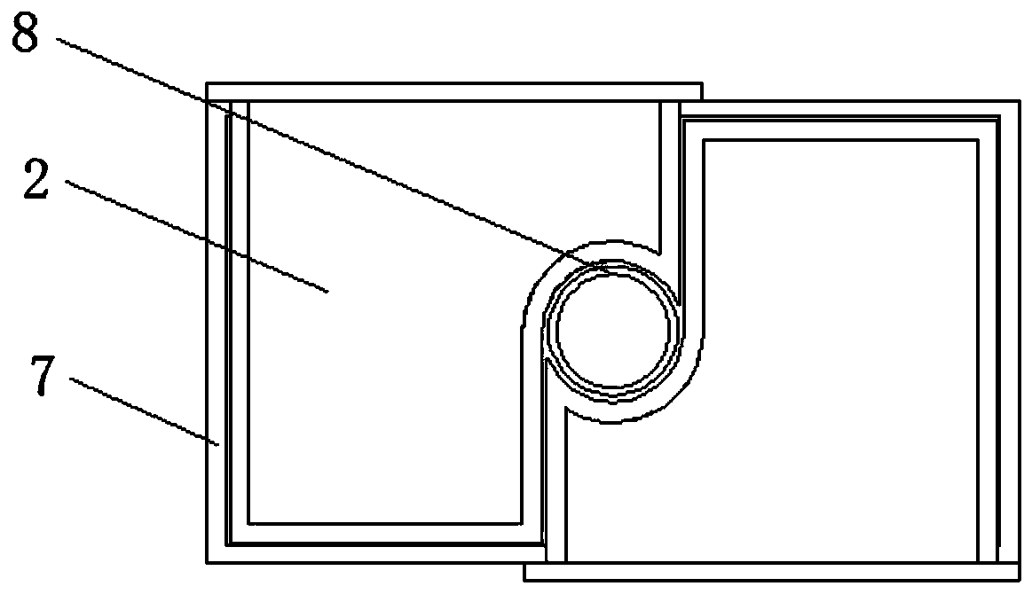
[0020] refer to Figure 1-2 , a boiler exhaust gas treatment device for environmental protection, comprising a water tank 1, a casing 7 is welded on the top of the water tank 1, and the top of the casing 7 is connected with an exhaust fan 6 through bolts, and the air outlet of the exhaust fan 6 is connected with an exhaust fan through a flange. The air pipe 5 and the side of the water tank 1 are welded with an air inlet pipe 12, and the air inlet pipe 12 is located inside the water tank 1, and one end is provided with a heat exchange coil 10, and the connection between the water tank 1 and the shell 7 is welded with a vertical pipe 8, and the vertical pipe 8 The bottom end of the housing 7 is welded to the nozzle of the heat exchange coil 10, the inner top of the housing 7 is connected with a mounting frame 4 by bolts, and the bottom end of the mounting frame 4 is connected with a multi-layer dust filter bag 3 by screws, and the two sides of the water tank 1 The water exchange...
Embodiment 2
[0027] refer to figure 1 with image 3 , a boiler exhaust gas treatment device for environmental protection, further, the inner wall of the housing 7 is welded with a plurality of support blocks, and the mounting frame 4 is installed above the support blocks through springs;
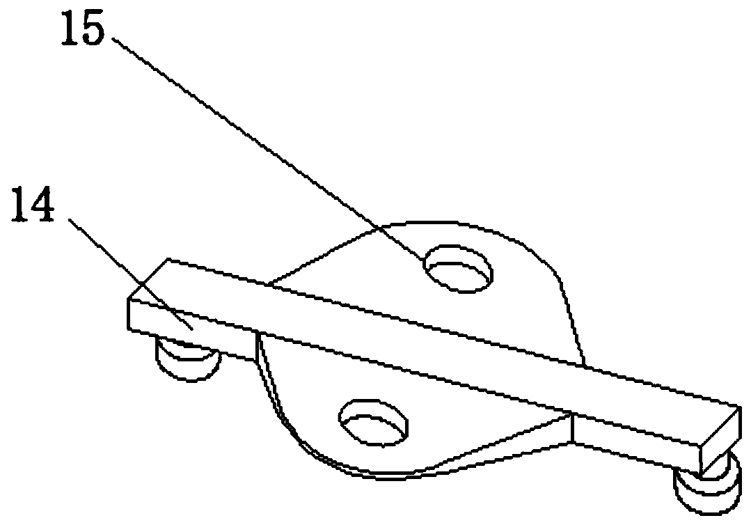
[0028] The top of mounting frame 4 is connected with movable rod 14 by spring and bolt, and the bottom two ends of movable rod 14 are all connected with percussion block by bolt, and the both sides of movable rod 14 are all welded with wind plate 15.
[0029] Working principle: Compared with Example 1, the installation frame 4 is installed on the housing 7 through the spring and the support block, and the movable rod 14 and the knocking block are installed on the top of the installation frame 4 through the spring. When flowing through the suction effect of the exhaust fan 6, the air flow drives the movable rod 14 to swing through the wind plate 15, and then uses the knocking block to knock the mounting ...
PUM
 Abstract
Description
Claims
Application Information
 - R&D
- Intellectual Property
- Life Sciences
- Materials
- Tech Scout
- Unparalleled Data Quality
- Higher Quality Content
- 60% Fewer Hallucinations
Browse by: Latest US Patents, China's latest patents, Technical Efficacy Thesaurus, Application Domain, Technology Topic, Popular Technical Reports.
© 2025 PatSnap. All rights reserved.Legal|Privacy policy|Modern Slavery Act Transparency Statement|Sitemap|About US| Contact US: help@patsnap.com