Device and method for measuring collision process in laser shock high-speed forming of plate

A technology of laser shock and laser forming, which is applied in the field of measurement, can solve problems such as measuring the contact time and the number of collisions that cannot be measured, measuring the speed of sheet metal movement and deformation, blocking and measuring laser pulses, etc., to achieve simple debugging, The effect of fast response and simple measurement equipment

Active Publication Date: 2020-06-26
ANHUI UNIVERSITY OF TECHNOLOGY
View PDF10 Cites 0 Cited by
  • Summary
  • Abstract
  • Description
  • Claims
  • Application Information

AI Technical Summary

Problems solved by technology

However, due to the extremely short period of contact between the plate and the mold, the impact occurs at the bottom of the cavity
Due to the occlusion of the mold, it is impossible for the existing VISAR laser velocity interferometer to measure the velocity of the plate movement and deformation from the bottom direction of the mold, let alone measure the contact time of collision and the number of collisions
Since the light pipe that transmits the laser pulse is placed in front of the mold when the laser induces a shock wave, there is no place for the VISAR laser velocity interferometer, and the high-pressure plasma generated by laser irradiation gathers in the mold cavity for a short time, which also blocks the The measurement laser pulses from VISAR make it difficult to reach the surface of the deformed sheet
At present, it is difficult to have ready-made tools to measure the time and number of collisions between the plate and the mold when the plate is bonded during the laser shock process

Method used


Image

  • Device and method for measuring collision process in laser shock high-speed forming of plate
  • Device and method for measuring collision process in laser shock high-speed forming of plate

Examples


Embodiment Construction

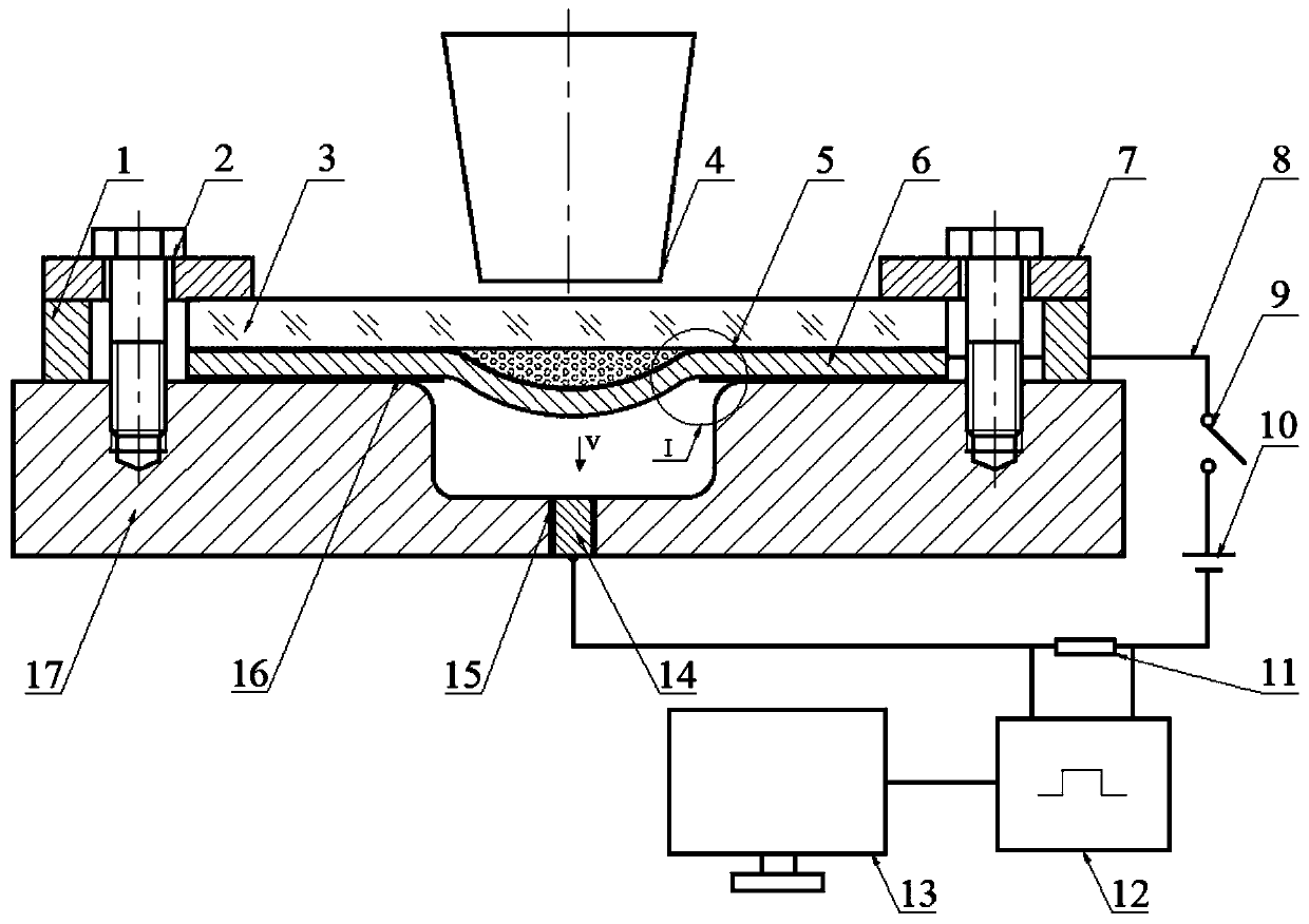
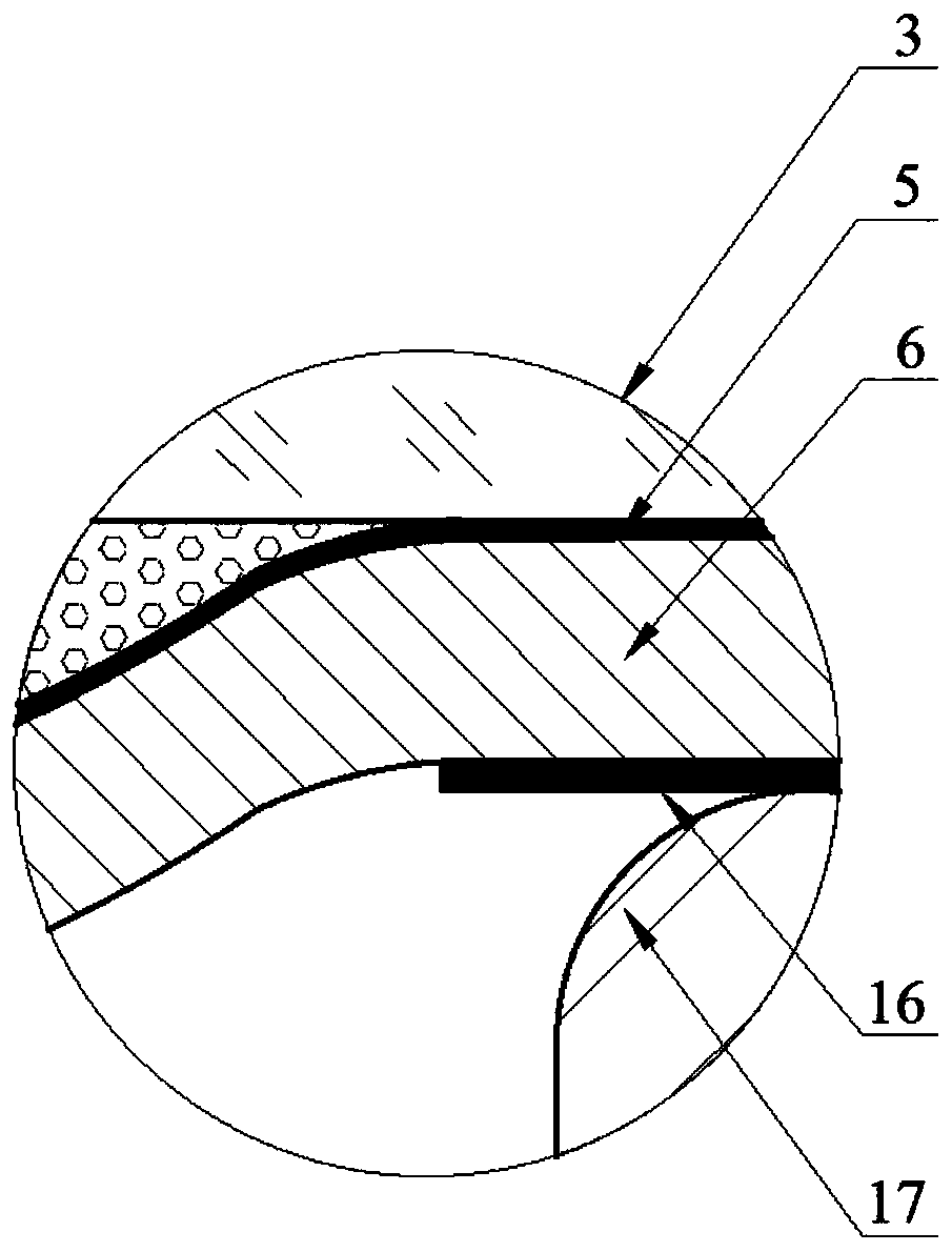
[0017] The invention provides a device and method for measuring the collision process in the laser shock high-speed forming of a sheet material. The device includes a laser forming system and a measuring system. The laser forming system includes a spacer block 1, a bolt 2, an optical glass 3, a laser 4, an absorption layer 5, a metal sheet 6, a pressing plate 7, a metal round bar 14, a barrier film 15, an insulating paper 16, and a concave mold 17. The measurement system includes a thin metal plate 6, a wire 8, a switch 9, a power supply 10, a fixed value resistor 11, a data acquisition recorder 12 and a computer (13). The wire 8 in the measurement system sequentially connects the metal sheet 6, the switch 9, the power supply 10, the fixed-value resistor 11 and the metal round bar 14 in series, and the two ends of the fixed-value resistor 11 are connected in parallel with the data acquisition recorder 12 through the wires. The recorder 12 is connected to the computer 13 through...


PUM


Abstract

The invention discloses a device and a method for measuring a collision process in laser shock high-speed forming of a plate, and belongs to the technical field of measurement. The device comprises alaser forming system and a measuring system, wherein the laser forming system comprises optical glass, a laser, an absorption layer, a metal sheet, a metal round bar, a barrier film, insulating paperand a female die. The method comprises the following steps of: firstly, enabling a metal die not to be in direct contact with the metal sheet and the metal round bar by adopting the insulating paper and the barrier film; correspondingly connecting the metal sheet and the metal round bar with a positive electrode and a negative electrode of a power supply; enabling the metal sheet to be in contactwith the metal round bar after being subjected to laser shock deformation; and conducting a measuring loop, wherein the number of generated voltage pulse signals is the collision frequency of the metal sheet moving at a high speed and the metal die, and the width of voltage pulses is the collision contact time. According to the method and the device, the collision process in laser shock high-speedforming of the plate can be accurately measured. The device has potential market application prospects.

Description

Technical field: [0001] The invention belongs to the field of measurement technology, and specifically relates to a device and method for measuring the number of collisions and collision contact time of a sheet during the process of attaching a sheet to a forming die under the action of a high-energy substance, and is particularly suitable for use in the high-speed forming process of the sheet under laser shock. Method to measure the collision process between the plate and the mold. Background technique: [0002] At present, laser shock forming has been widely used. The high strain rate laser shock forming technology has greatly improved the plasticity of materials that are difficult to form at room temperature, and can realize the forming of complex shapes of materials that are difficult to form at room temperature, such as titanium alloys. Laser shock forming belongs to high-speed forming. It has a remarkable feature: the sheet obtains kinetic energy and momentum from the high-...

Claims


Application Information

Patent Timeline
Patent Type & Authority Applications(China)
IPC IPC(8): B21D26/06B21C51/00
CPCB21D26/06B21C51/00
Inventor 张兴权陈剑剑苏海沙方进秀王会廷尹元德宋广生
Owner ANHUI UNIVERSITY OF TECHNOLOGY
Why Eureka
Try Eureka