Eureka AIR delivers breakthrough ideas for toughest innovation challenges, trusted by R&D personnel around the world.

Vertical vibration isolation device

A vibration damping device, vertical technology, applied to building components, high internal friction springs, shockproof, etc., can solve the problems of small vertical stiffness, harsh working environment, easy resonance and high-frequency vibration transmission, etc., to avoid torsion Deformation, broad application prospects, and the effect of improving installation efficiency

Inactive Publication Date: 2020-06-26
TONGJI UNIV
View PDF5 Cites 4 Cited by
  • Summary
  • Abstract
  • Description
  • Claims
  • Application Information

AI Technical Summary

Problems solved by technology

[0003] On the other hand, for large and medium-sized precision instruments sensitive to vibration in buildings along the subway line, the working environment is harsh, and the quality of their operation directly affects the safety and data reliability of the instruments. However, the vertical vibration caused by urban rail transit The vibration will be transmitted to the mechanical equipment through the workbench, which will affect the normal operation of the mechanical equipment, so it is also necessary to take measures to reduce the vibration of large and medium-sized mechanical equipment
[0004] For buildings that are sensitive to vertical vibration along the subway line, rubber bearings and metal spring devices are mainly used at present. The axial stiffness is small. For buildings along the subway line, more vibration damping devices need to be connected in parallel. It is effective for low-frequency vibration isolation, but it is easy to generate resonance and propagate high-frequency vibration. Other measures need to be used to cooperate with vibration isolation
[0005] Metal spring vibration isolation is mostly used for large and medium-sized mechanical equipment. Because of the single positive and negative stiffness frequency of the spring, the vibration damping effect of the vibration damping mechanism is not significant, and it has a long vibration damping period, which will affect the stability of the equipment and cannot be directly Applied to large and medium-sized machinery and equipment along rail transit

Method used


Image

  • Vertical vibration isolation device
  • Vertical vibration isolation device
  • Vertical vibration isolation device

Examples


Embodiment 1

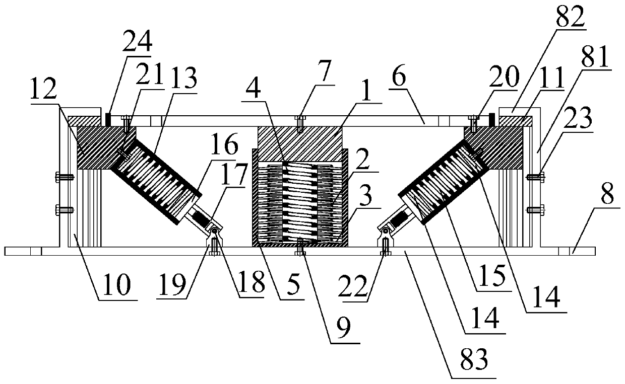
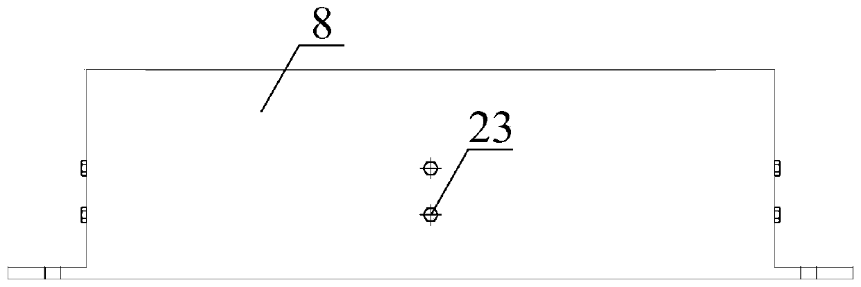
[0052] Embodiment 1: see figure 1 and figure 2

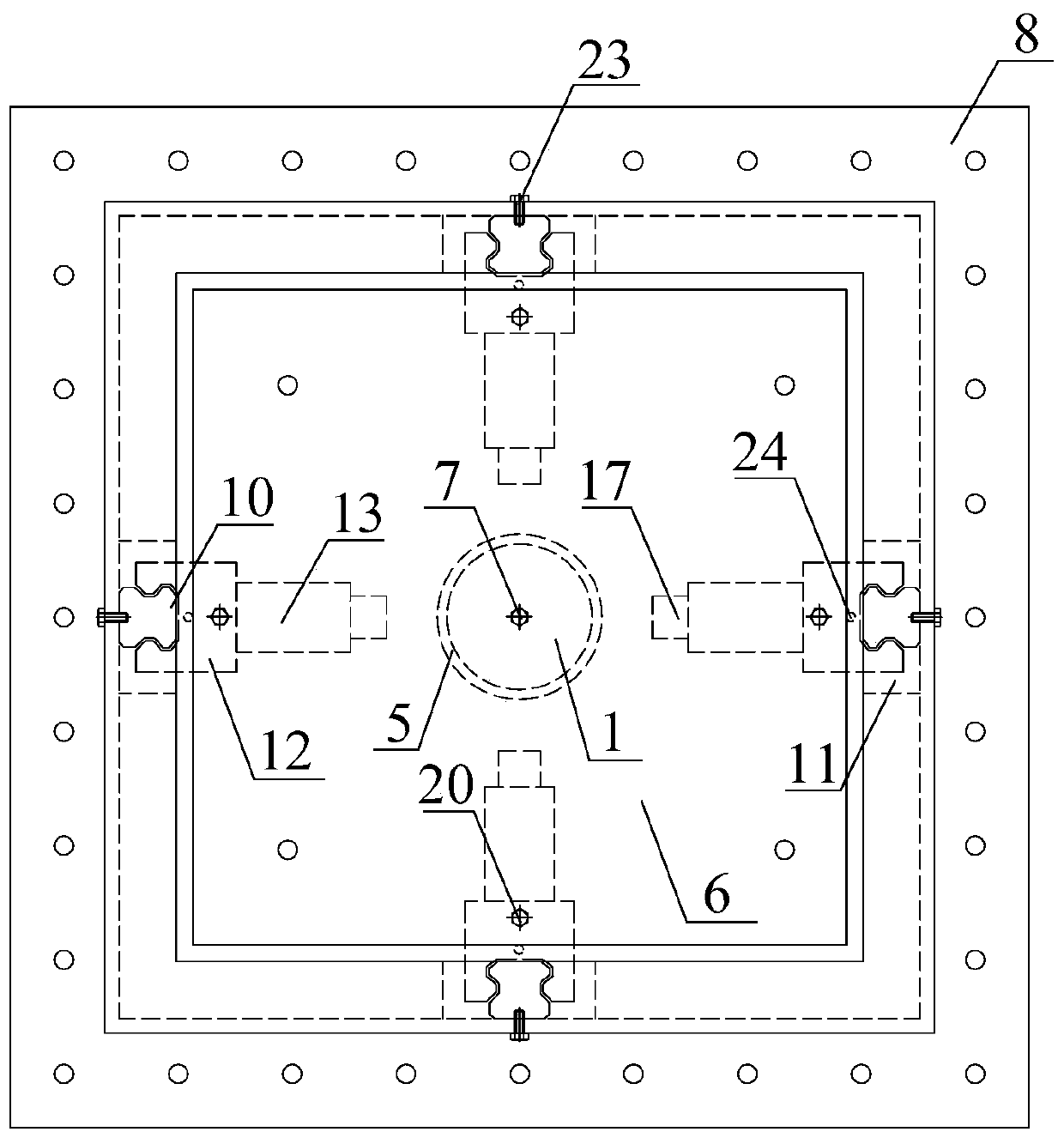
[0053] see image 3 , as an example, this embodiment is provided with 4 sets of damping devices. Under the action of vertical vibration, the 4 sets of damping devices are linked together to reduce the vertical vibration. The 4 sets of devices are placed symmetrically to prevent the structure or equipment Unsteady.

[0054] Figure 4 It is a schematic diagram of the construction of an adaptive stiffness element, and a schematic diagram of the construction of a disc spring group, see Figure 5 , see the three-dimensional view of the preloaded rectangular spring Figure 6 . The positioning loading ring 2 and the disc spring 3 work in parallel to provide vertical negative stiffness, the pre-compressed rectangular spring 4 is in contact with the actuating block 1, and the disc spring group and the actuating block 1 reserve a gap of 5-8mm to ensure the pre-compressed rectangular The larger positive stiffness provided by the sp...


PUM


Abstract

The invention discloses a vertical vibration isolation device. The vertical vibration isolation device mainly comprises an upper connecting plate, an adaptive stiffness unit, slidable oblique rectangular compression spring units and a lower connecting plate. The adaptive stiffness unit is mainly composed of a positioning loading ring, a belleville spring and a pre-compressed rectangular spring, wherein the positioning loading ring and the belleville spring work in parallel to provide vertical negative stiffness, the pre-compressed rectangular spring provides vertical positive stiffness, and the positioning loading ring, the belleville spring and the pre-compressed rectangular spring work together to generate adaptive stiffness; and the slidable oblique rectangular compression spring unitsare each composed of a directional linear guide rail, an oblique rectangular compression spring and a universal joint, vertical sliding blocks move down along the directional linear guide rails to cause axial compression deformation of the oblique rectangular springs, and energy is dissipated through the mutual conversion of elastic potential energy and kinetic energy. The adaptive stiffness unitand the slidable oblique rectangular compression spring units work in parallel, collaboratively deform and jointly achieve vertical vibration isolation. The vertical vibration isolation device can bewidely applied to buildings or large and medium-sized mechanical equipment with high requirements for vibration reduction and near rail transit.

Description

technical field [0001] The invention relates to a vertical vibration isolation device, which belongs to the technical field of vibration isolation in civil engineering and mechanical engineering. Background technique [0002] With the increase of my country's urbanization rate, urbanization is gradually developing towards urbanization, and urban land is in short supply. The development of rail transit has become the most effective way to solve urban traffic. Rail transit lines will pass through populated areas and some urban buildings, which is bound to It brings vibration to the personnel and equipment in the building. In particular, for rail transit, the foundation of the superstructure is directly arranged on the vibration source excitation caused by the subway, resulting in a greater impact on the environment than the buildings along the track. , which brings the problem of vibration comfort caused by urban rail transit, it is necessary to take corresponding vibration cont...

Claims


Application Information

Patent Timeline
Patent Type & Authority Applications(China)
IPC IPC(8): F16F3/12E04B1/98E04H9/02
CPCE04B1/98E04H9/021F16F3/12
Inventor 周颖张增德陈鹏刘浩
Owner TONGJI UNIV
Why Eureka
Eureka Blog
Learn More