
Shaping machine

A planer and bed technology, which is applied in the direction of planer/slotting machine, slotting machine, metal processing equipment, etc., can solve the difficulty of stabilizing the processing effect of the planer, unsolved problems of speed stability of the planer, and the processing quality effect of the planer In order to avoid the influence of static friction, improve the processing effect and improve the processing efficiency

Active Publication Date: 2020-06-30
ZHEJIANG ZHIHENG MACHINE TOOLS CO LTD
View PDF7 Cites 0 Cited by
  • Summary
  • Abstract
  • Description
  • Claims
  • Application Information

AI Technical Summary

Problems solved by technology

[0003] In the working process of the planer, in order to improve the quality of the planing process, the planer is expected to move at a constant speed during the processing operation. However, the main movement of the planer is mostly based on the transmission of the crank rocker mechanism, so the moving speed of the ram is not stable. Even, it is difficult to achieve uniform motion requirements, which will affect the processing quality of the planer
[0004] There are also some technical solutions about planers in the prior art. For example, a Chinese patent with application number 2017100447593 discloses a planer: including a base, a bed, a workbench, a main motion mechanism and a workbench feed mechanism. The main motion mechanism includes a ram fixedly installed on the bed, a first motor arranged on the upper end of the ram, and a boring and milling spindle grinding head arranged at the front end of the ram, the first motor and the boring and milling spindle grinding head There is a synchronous transmission device between them, the bottom end of the grinding head of the boring and milling spindle is provided with a milling cutter disc; the feeding mechanism of the worktable includes a gear transmission mechanism arranged on the bed, and one end is arranged on the bed, and the other end is arranged on the bed. The pulley transmission mechanism on the workbench; the technical scheme sets the main movement mechanism of the planer and the feed mechanism of the workbench as two completely independent mechanisms, so that the main movement and the feed movement of the planer can be carried out simultaneously, improving The processing efficiency is improved; the main movement mechanism of the planer is fixed on the bed, so that its main movement is relatively stable and the machining accuracy is improved; but the speed stability problem of the planer in use when feeding is not solved in this technical solution; It makes it difficult to ensure the stability of the processing effect of the planer in this technical solution

Method used


Image

  • Shaping machine
  • Shaping machine
  • Shaping machine

Examples


Embodiment approach

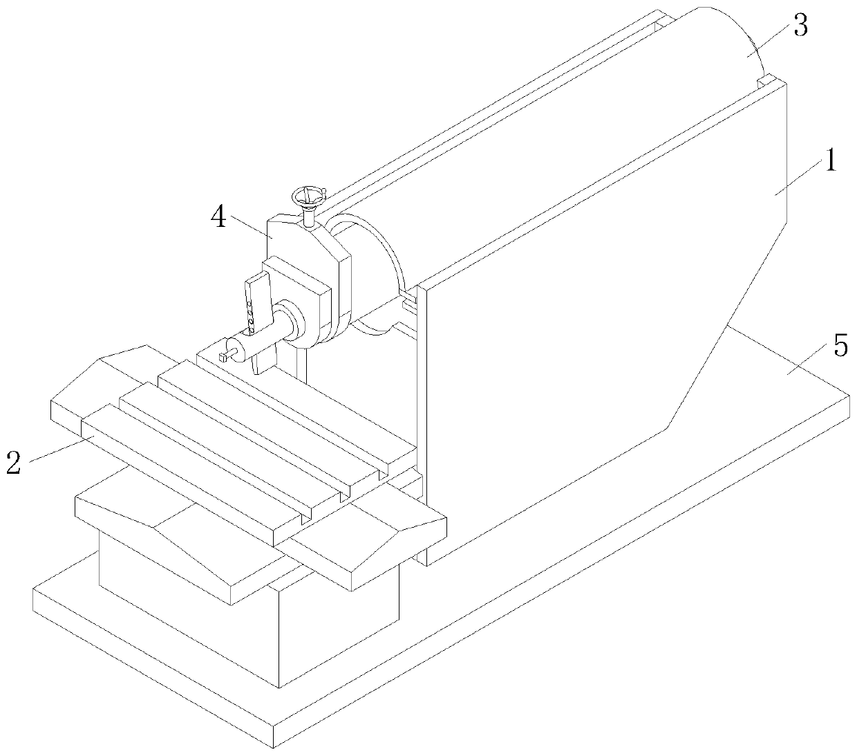
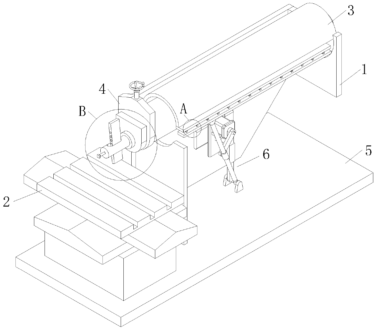
[0028] As an embodiment of the present invention, the upper part of the bed 1 is provided with a slide rail 13, and the slide rail 13 is provided with roller bearings 131, and the roller bearings 131 are evenly distributed on the slide rail 13, and the roller bearings The ram 3 is slidingly installed on the 131; when working, the ram 3 is directly slidably installed on the upper part of the bed 1, and the relatively smooth plane between the bottom of the ram 3 and the bed 1 is used as a sliding contact surface, and the ram 3 reciprocates During the movement, it is necessary to repeatedly overcome the static friction force to achieve the effect of the reciprocating movement of the ram 3, which causes additional loss to the output power of the linkage mechanism 6; through the roller bearing 131 arranged on the slide rail 13 of the bed 1, When the slide rail 13 reciprocates on the bed 1, the rolling contact with the roller bearing 131 avoids the influence of static friction betwee...


PUM


Abstract

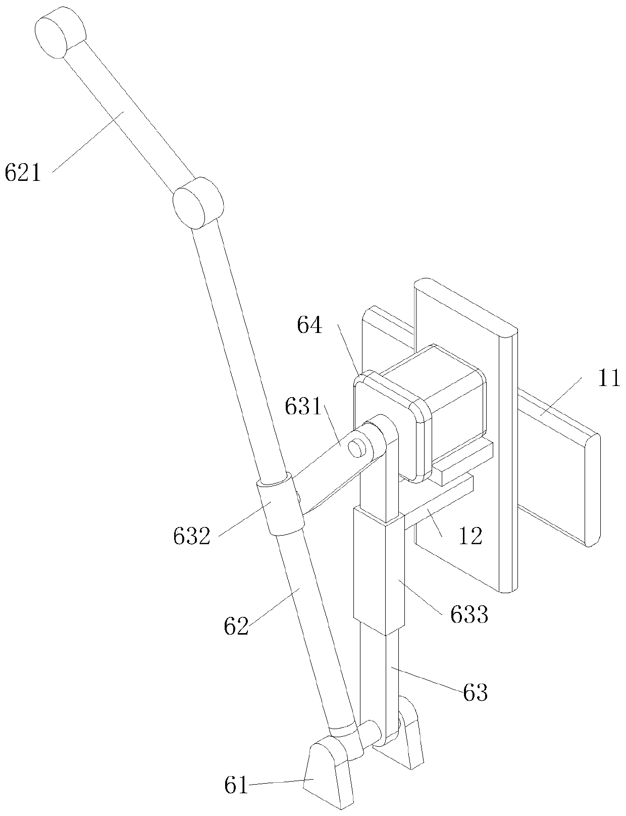
The invention relates to the technical field of machine tool machining and mechanical transmission, in particular to a shaping machine. The shaping machine comprises a lathe bed, a workbench, a ram, atool post and a controller; the lower portion of the lathe bed is provided with a base, the outer side of the lathe bed is provided with the workbench, the upper portion of the lathe bed is providedwith the ram, and the end, facing towards the workbench, of the ram is provided with the tool post; in the working process of the shaping machine, the feeding speed of the tool post is unbalanced dueto driving of a connection rod mechanism, the low output power of a servo motor is hardly to directly drive the shaping machine to move, then, the machining effect of the shaping machine on a workpiece is influenced, thus, through a strut arranged in the connection rod mechanism, the torque of acting force of a driving rod to a swing rod is improved, a strut rotationally connected to the servo motor serves as supporting to operation of the connection rod, driving control of the servo motor at low power on power input of the connection mechanism is achieved, then, the feed rate of the tool postis stabilized, and accordingly the machining effect of the shaping machine is improved.

Description

technical field [0001] The invention relates to the technical field of machine tool processing and mechanical transmission, in particular to a planer. Background technique [0002] Bullhead planer is a kind of planer that makes linear reciprocating motion. It is named because the tool holder at the front end of the ram is shaped like a bull's head; bullhead planer is mainly used for small and medium-sized bullhead planers. planing planes, forming surfaces and grooves on small and medium-sized workpieces in small batch production; for the introduction of the planer, see: Wang Bing et al., Design space and performance map of a new type of mechanism [J], Mechanical Transmission, 2017 (No. 6). 15-20. [0003] In the working process of the planer, in order to improve the quality of the planing process, the planer is expected to move at a constant speed during the processing operation. However, the main movement of the planer is mostly based on the transmission of the crank rocke...

Claims


Application Information

Patent Timeline
IPC IPC(8): B23D7/06B23D7/10
CPCB23D7/06B23D7/10
Inventor 薛继纲张小飞张强
Owner ZHEJIANG ZHIHENG MACHINE TOOLS CO LTD
Learn More