Energy recovery-based damping device and system and train

A technology of energy recovery and vibration damping device, which is applied in the direction of circuit device, device for lateral relative movement between chassis and bogie, battery circuit device, etc., can solve problems such as aggravated system loss and reduced energy recovery efficiency, and achieves improved The effect of bending resistance, avoiding instability, and reducing radial dimensions

Pending Publication Date: 2020-07-03
SOUTHWEST UNIVERSITY +2
View PDF7 Cites 2 Cited by
  • Summary
  • Abstract
  • Description
  • Claims
  • Application Information

AI Technical Summary

Problems solved by technology

The repeated contact and separation process of the pillow spring and the screw rod will generate a dynamic im

Method used


Image

  • Energy recovery-based damping device and system and train
  • Energy recovery-based damping device and system and train
  • Energy recovery-based damping device and system and train

Examples


Embodiment 1

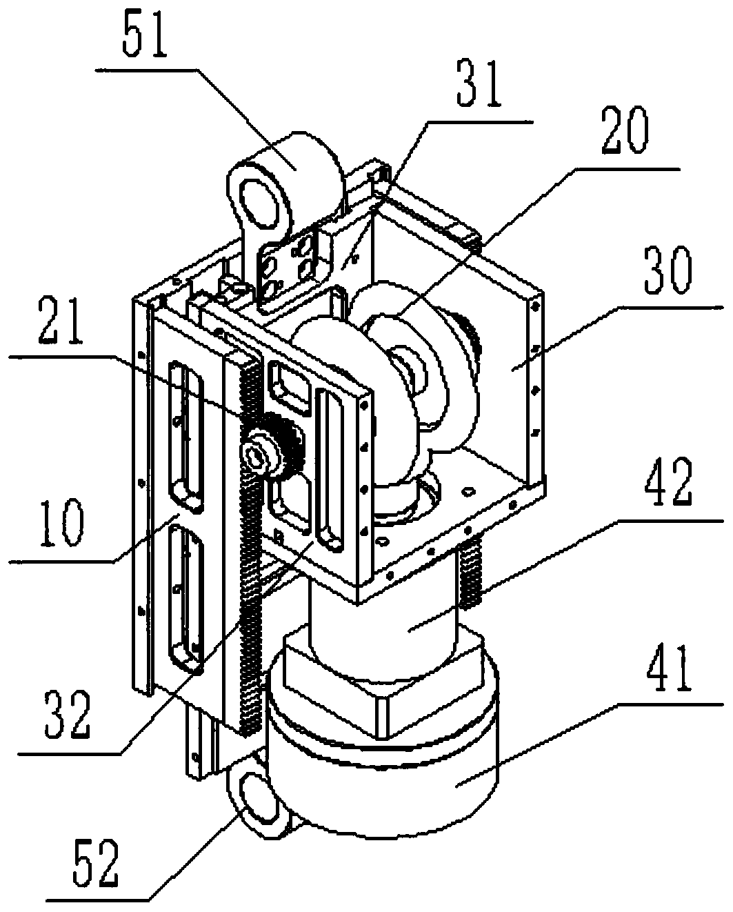
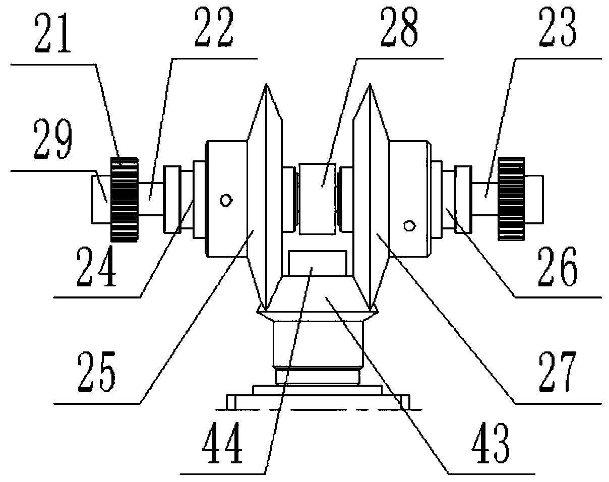
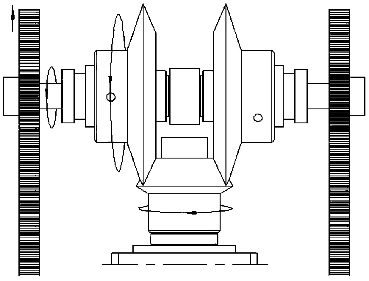
[0038] This embodiment provides a vibration damping device based on energy recovery, such as figure 1 As shown, it includes a U-shaped double tooth assembly 10 , a transmission assembly 20 , a mounting plate assembly 30 and a DC generator 41 . like figure 1 and figure 2 As shown, the transmission assembly 20 includes a driving shaft, a first gear 21 arranged at both ends of the driving shaft, and a second gear arranged in the middle of the driving shaft through a one-way bearing. The mounting plate assembly 30 includes a lower base plate 31 and two mounting plates 32 installed on the left and right sides of the lower base plate 31, the driving shaft is rotatably arranged on the mounting plate 32, and the U-shaped double tooth assembly 10 is slidably connected to the lower base plate 31. Two arms of the U-shaped double-tooth assembly 10 are provided with racks, and the racks are meshed with the first gear 21 . The rack can be arranged on the top of the two arms or on the si...

Embodiment 2

[0050] This embodiment provides an energy recovery-based vibration reduction system, including the energy recovery-based vibration reduction device in Embodiment 1, and also includes a DC boost module and a supercapacitor energy storage module. The energy recovery and vibration damping device performs vibration reduction through the resistance torque provided by the DC generator during rotation, while the DC generator converts mechanical energy into electrical energy, and the DC boost module filters and boosts the unstable electrical signal generated by the DC generator processing, the supercapacitor energy storage module stores and distributes electrical energy.

Embodiment 3

[0052] This embodiment provides a train, including the energy recovery-based vibration reduction system in Embodiment 2, wherein the energy recovery-based vibration reduction device is connected with the side frame and the bolster of the train bogie.


PUM


Abstract

The invention discloses an energy recovery-based damping device and system and a train. The energy recovery-based damping device comprises a U-shaped double-tooth component, a transmission component,a mounting plate component and a direct current electric generator; the transmission component comprises a driving shaft, first gears arranged at two ends of the driving shaft, a second gear arrangedin the middle of the driving shaft through a one-way bearing; the mounting plate component comprises a lower bottom plate and mounting plates mounted on the left side and the right side of the lower bottom plate; the driving shaft is rotatably arranged on the mounting plate; the lower bottom plate is arranged on the bottom surface of the U-shaped double-tooth component in a sliding manner; gear racks are arranged on two supporting arms of the U-shaped double-tooth component; the gear racks are engaged with the first gears; when the U-shaped double-tooth component slides relative to the lower bottom plate, the gear racks drive the first gears to rotate; and the second gear is connected to an input end of the direct current electric generator. According to the energy recovery-based damping device and system and the train, the structural strength of the damping device is improved, and the instability of the damping device caused by eccentric force is avoided, so that the work efficiency of the energy recovery-based damping device is improved and the service life of the energy recovery-based damping device is prolonged.

Description

technical field [0001] The invention relates to the field of vibration damping devices, in particular to a vibration damping device and system based on energy recovery. Background technique [0002] At present, the shock absorbers used in most vehicles mainly consider two aspects of vibration isolation and energy dissipation. Existing shock absorbers mainly convert mechanical vibration energy into heat energy through friction or other means and dissipate it in the air, which cannot recycle the mechanical energy in this process, resulting in energy waste. However, many of the existing freight trains are not equipped with power systems, which brings great challenges to the monitoring of the safety status of freight trains. The track condition of freight railway is generally worse than that of passenger railway, and the vibration of trains is more severe during operation. Convert the vibration energy during the operation of freight trains into electrical energy, and use it fo...

Claims


Application Information

Patent Timeline
IPC IPC(8): F03G7/08F03G3/00B61F5/12H02J7/32H02J7/34
CPCB61F5/12F03G3/00F03G7/08H02J7/32H02J7/345
Inventor 高鸣源王平肖杰灵王源王沂峰李守太邢东郭文兰郝崇杰郭凯陈志平卢玉田曹政祥张俊琴王玉道赵玉波赵雁冰黄光宇赵迎军刘书银张军解文喜马林白付维周先平黄宏伟周康庞川宾田野王新华
Owner SOUTHWEST UNIVERSITY
Why Eureka
Try Eureka