Low-temperature plasma discharge device and hydrogen sulfide decomposition method
A low-temperature plasma and discharge device technology, applied in the field of ion chemistry, can solve the problems of low hydrogen sulfide conversion rate and high energy consumption for decomposition
- Summary
- Abstract
- Description
- Claims
- Application Information
AI Technical Summary
Problems solved by technology
Method used
Image
Examples
Embodiment 1
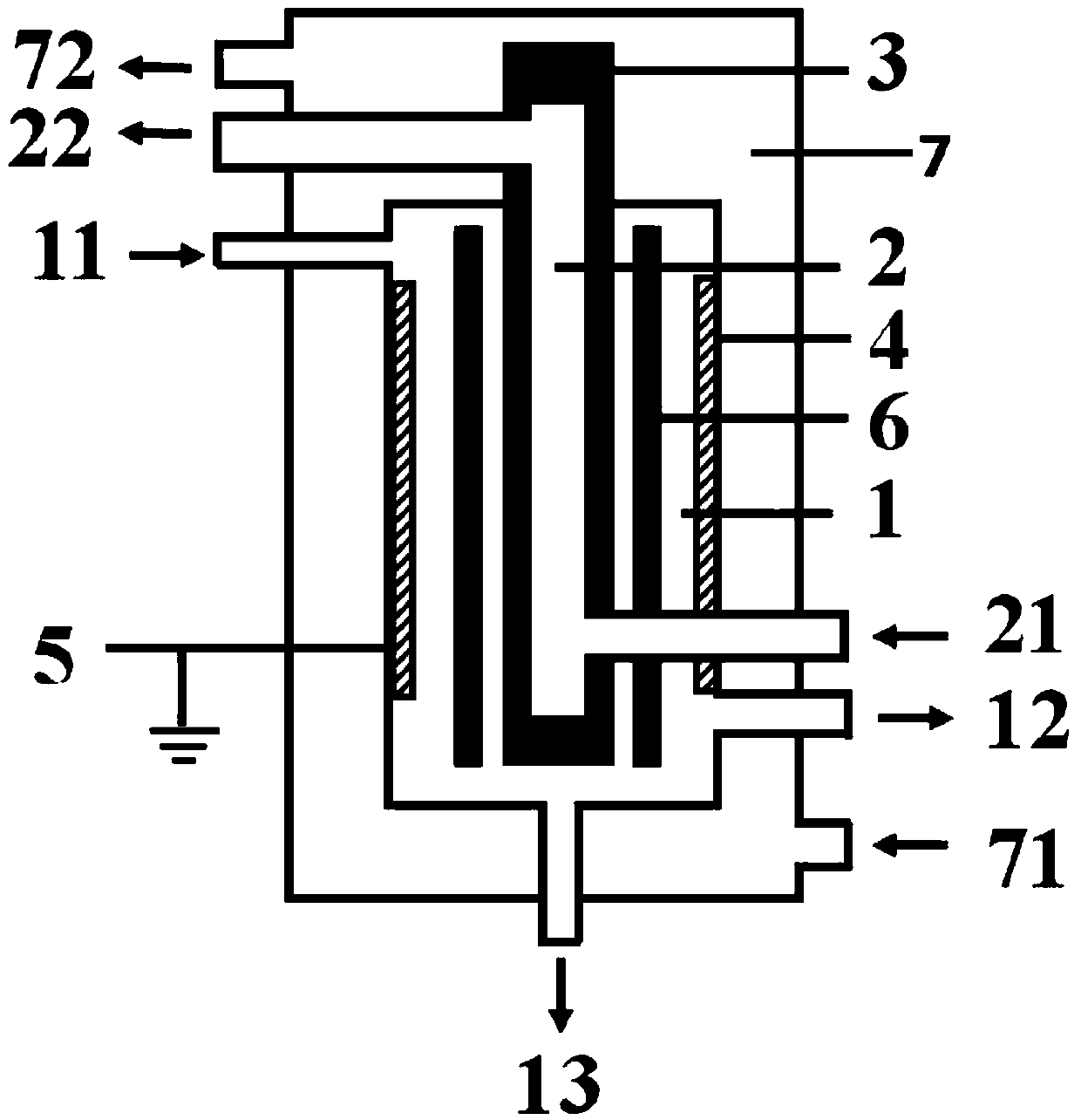
[0110] use figure 1 The shown low-temperature plasma reactor performs hydrogen sulfide decomposition reaction, and the specific structure and structural parameters of the low-temperature plasma reactor are as follows:
[0111] The reactor includes:
[0112] A first cavity, the first cavity is respectively provided with a first inlet, a gas product outlet and a liquid product outlet, wherein the side wall of the first cavity is formed by an external electrode, and forms the outer electrode The material is stainless steel foil, and the external electrode is grounded;
[0113] The second cavity, the second cavity is nested inside the first cavity, and the second cavity is respectively provided with a second inlet and a second outlet, and the side walls of the second cavity are all Formed by internal electrodes, the material forming the internal electrodes is stainless steel, and the internal electrodes are connected to a high-voltage power supply;
[0114] a third cavity, the ...
Embodiment 2
[0142] The present embodiment adopts the plasma reactor similar to embodiment 1 to carry out the decomposition reaction of hydrogen sulfide, the difference is, in the present embodiment:
[0143] The outer electrode is arranged on the inner side wall of the first cavity, and the material forming the outer electrode is stainless steel metal foil; and the outer electrode is connected to a high-voltage power supply, and the inner electrode is grounded;
[0144] L 2 with the thickness of the barrier dielectric D 1 ratio of 1:1; and H 1 :L 3 =1:280.
[0145] In this embodiment, H is introduced into the first cavity of the low-temperature plasma reactor from the first inlet. 2 S / H 2 mixed gas, where H 2 The volume fraction of S is 83%, the flow rate of the mixed gas is controlled so that the average residence time of the gas in the discharge area is 18.4s, and the reaction pressure in the first cavity of the reactor is maintained at 0.07MPa in this embodiment. h 2 S / H 2 Aft...
Embodiment 3
[0149] The present embodiment adopts the plasma reactor similar to embodiment 1 to carry out the decomposition reaction of hydrogen sulfide, the difference is, in the present embodiment:
[0150] The outer electrode is arranged around the inner side wall of the first cavity, the material forming the outer electrode is stainless steel metal foil, the outer electrode is grounded, and the inner electrode is connected to a high-voltage power supply;
[0151] L 2 with the thickness of the barrier dielectric D 1 ratio of 15:1; and H 1 :L 3 =1:400.
[0152] All the other specific structures and structural parameters are the same as in Example 1.
[0153] In this embodiment, H is introduced into the first cavity of the low-temperature plasma reactor from the first inlet. 2 S / N 2 mixed gas, where H 2 The volume fraction of S is 30%, the flow rate of the mixed gas is controlled so that the average residence time of the gas in the discharge area is 15.2s, and the reaction pressure...
PUM
 Abstract
Description
Claims
Application Information
 - R&D
- Intellectual Property
- Life Sciences
- Materials
- Tech Scout
- Unparalleled Data Quality
- Higher Quality Content
- 60% Fewer Hallucinations
Browse by: Latest US Patents, China's latest patents, Technical Efficacy Thesaurus, Application Domain, Technology Topic, Popular Technical Reports.
© 2025 PatSnap. All rights reserved.Legal|Privacy policy|Modern Slavery Act Transparency Statement|Sitemap|About US| Contact US: help@patsnap.com

