Padding device for producing textile

A textile and padding technology, which is applied in the field of textile production, can solve the problems of recycling and waste of dyeing liquid, impossibility of fabric padding, and inability to accurately control the force of pressing rollers, etc.

Inactive Publication Date: 2020-07-07
桐乡市灵僧服装有限公司
View PDF1 Cites 5 Cited by
  • Summary
  • Abstract
  • Description
  • Claims
  • Application Information

AI Technical Summary

Problems solved by technology

[0005] But above-mentioned technical scheme still has many shortcomings when practical application;
[0006] 1. Because the padding equipment pads the stretching tension of the cloth through the cloth inlet wheel, cloth outlet wheel and pad stick, after the solution is carried on the inner cavity of the pad dyeing pool, the weight of the solution on the cloth surface after passing through the pad The percentage of the original fabric weight before padding is relatively large, and the fabric cannot be fully padded;
[0007] 2. Since the stretching tension of the fabric is padded through the peripheral cloth inlet wheel, cloth outlet wheel and pad roller, the strength of the roller cannot be precisely controlled, resulting in an uncontrollable pass rate, and the padding roller There will still be dyeing liquid dripping from the cloth outlet wheel with peripherals, and the dyeing liquid cannot be recycled, resulting in waste, increasing material costs and cleaning workload

Method used


Image

  • Padding device for producing textile
  • Padding device for producing textile
  • Padding device for producing textile

Examples


Embodiment 1

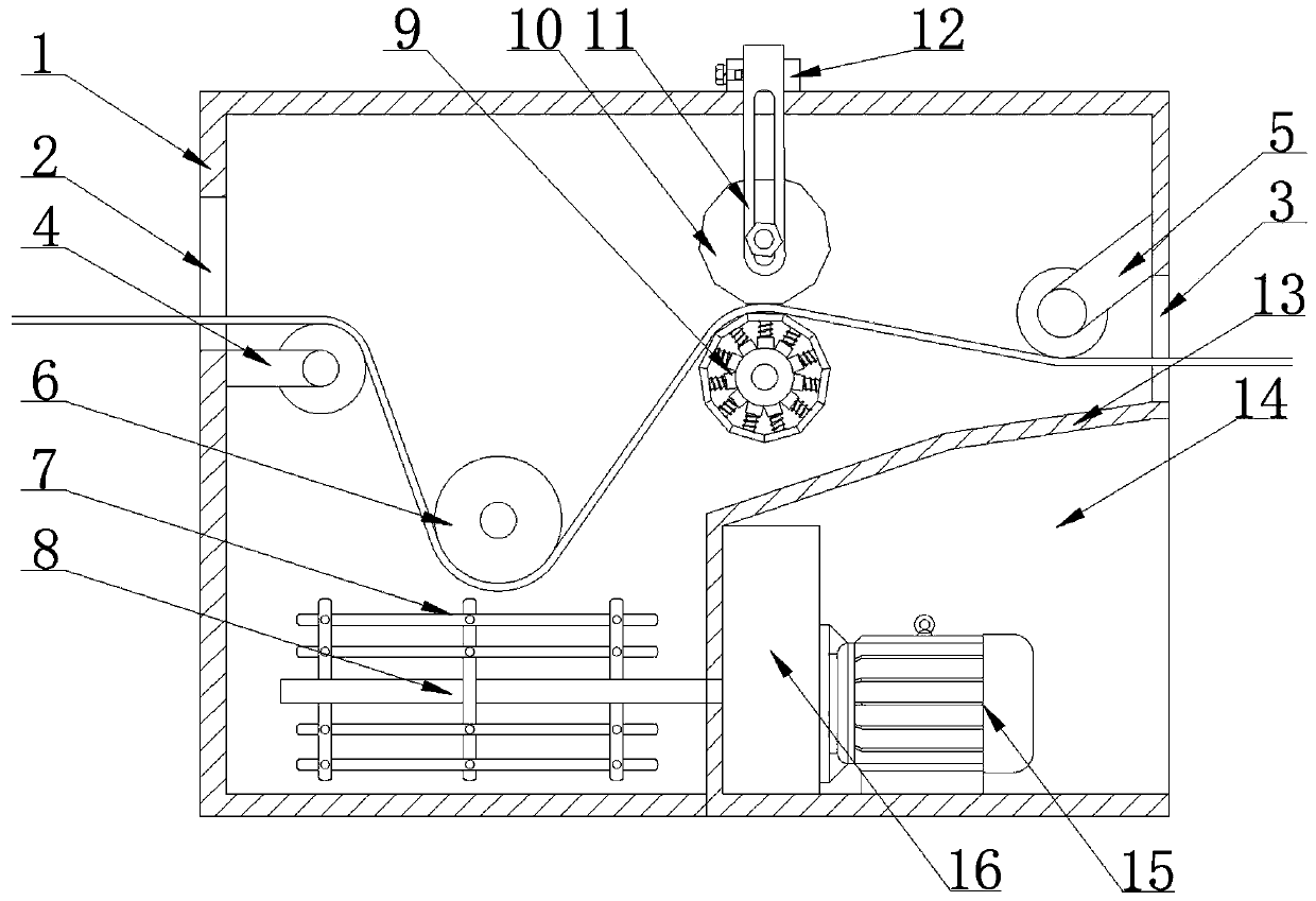
[0029] as attached Figure 1-4 The shown padding equipment for textile production includes a pad dyeing pool 1, and the left and right sides of the pad dyeing pool 1 are respectively provided with a feed inlet 2, a discharge port 3, and ends of the feed port 2 and the discharge port 3. The cloth inlet wheel 4 and the cloth outlet wheel 5 which are located inside the pad dyeing pool 1 are fixedly installed on the upper part, and the dipping roller 6 and the pad dyeing stick 9 are installed in rotation inside the pad dyeing pool 1, and the bottom end of the discharge port 3 is fixedly installed. There is a partition 13, the inner side of the partition 13 and the pad dyeing pool 1 form a closed cavity, the outer side of the partition 13 is provided with a power chamber 14, and the outer side of the partition 13 is fixedly installed with a transmission box 16 located inside the power chamber 14, The output end of the transmission box 16 is fixedly connected with the stirring shaft...

Embodiment 2

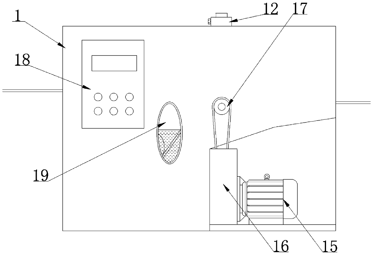
[0039] The difference with the above-mentioned embodiment is embodied in: the appended Figure 5 Shown: includes a pad dyeing pool 1, the left and right sides of the pad dyeing pool 1 are respectively provided with a feed port 2 and a discharge port 3, and the ends of the feed port 2 and the discharge port 3 are fixedly installed with The cloth inlet wheel 4 and the cloth outlet wheel 5 located inside the pad dyeing pool 1 are equipped with dipping rollers 6 and pad dyeing sticks 9 rotating inside the pad dyeing pool 1, and the bottom end of the discharge port 3 is fixedly installed with Partition 13, the inner side of the partition 13 and the pad dyeing pool 1 form a closed cavity, the outside of the partition 13 is provided with a power chamber 14, and the outside of the partition 13 is fixedly installed with a The transmission box 16, the output end of the transmission box 16 is fixedly connected with the stirring shaft 8 located inside the pad dyeing pool 1, and one end of ...


PUM


Abstract

The invention discloses a padding device for producing a textile, and particularly relates to the field of textile production. The padding device comprises a pad-dyeing pool, wherein the left side andright side of the pad-dyeing pool are provided with a feeding hole and a discharge hole respectively; the interior of the pad-dyeing pool is rotationally provided with a liquid dipping roller and a pad-dyeing stick; the bottom end of the discharge hole is provided with a baffle plate; the outer side of the baffle plate is provided with a transmission case; the two ends of the top surface of the pad-dyeing pool are provided with a fixing sleeve block; the interior of the fixing sleeve block is connected to an adjustment supporting plate in a sleeving manner; and the surface of the adjustment supporting plate is provided with a pressure applying roller. According to the padding device, by arranging the mechanisms of the pressure applying roller and the pad-dyeing stick, the extrusion performed on the residual liquid of dip-dyed cloth is realized by utilizing extrusion force generated between the pressure applying roller and the pad-dyeing stick, to achieve a dewatering purpose; further,the extrusion force is enabled to be controllable by the adjustable pressure applying roller; a pressure sensor and a control module are arranged; the pressure change can be intuitively observed; thepad-dyeing stability of the padding device to the dip-dyed cloth is guaranteed; the cloth is enabled to be consistent in color pad-dyeing effect; the color-difference change does not exist; and the product quality is improved.

Description

technical field [0001] The invention relates to the technical field of textile production, more specifically, the invention is a padding equipment for textile production. Background technique [0002] Padding is a process of dip-dyeing cotton or polyester-cotton knitted fabrics with biological enzymes and pressing out the excess water in the dyed products. It belongs to the technical field of knitted fabric pretreatment in the printing and dyeing industry. The padding machine equipment is suitable for water-containing circular The drum fabric is subjected to padding and padding auxiliary treatment. The padding machine is often used as a device to remove excess water on the washed fabric before drying. [0003] Existing pad dyeing devices usually use a pad dyeing liquid tank. Usually, the working solution in the pad dyeing liquid tank is small and does not flow. It is only necessary to immerse the textile in the working solution for pad dyeing, which affects the quality of th...

Claims


Application Information

Patent Timeline
Patent Type & Authority Applications(China)
IPC IPC(8): D06B3/18D06B23/20
CPCD06B3/18D06B23/20
Inventor 陈佳敏吴奇勋
Owner 桐乡市灵僧服装有限公司
Why Eureka
Try Eureka