Vacuum cup grinding production line

A thermos cup and production line technology, applied in the direction of grinding machines, belt grinders, grinding feed movement, etc., can solve the problems of low processing efficiency, affecting the health of operators, environmental pollution, etc.

Pending Publication Date: 2020-07-10
浙江珂斯顿机器人科技有限公司
View PDF0 Cites 4 Cited by
  • Summary
  • Abstract
  • Description
  • Claims
  • Application Information

AI Technical Summary

Problems solved by technology

However, manual grinding and polishing has two major technical drawbacks
First, manual grinding and polishing will waste a lot of manpower, and limited by the work experience of the operator, the quality stability of the surface grinding and polishing of the thermos cup is extremely poor
Moreover, the length and position of the burrs before different vacuum cups are different, which means that there are great differences in the thermos cups. After the thermos cups are processed, it is very easy to have inconsistent grinding sizes due to insufficient or excessive grinding, or the phenomenon of polishing There are differences in the effect, resulting in frequent rework of the thermos cup after grinding and polishing
Second, the processing efficiency of manual grinding and polishing is low, which is far from meeting the increasing market demand. A large amount of flying chips and noise are generated during the grinding process, which seriously affects the health of operators and causes environmental pollution. Therefore, The polishing method of the existing thermos cup still needs to be further improved

Method used


Image

  • Vacuum cup grinding production line
  • Vacuum cup grinding production line
  • Vacuum cup grinding production line

Examples


Embodiment Construction

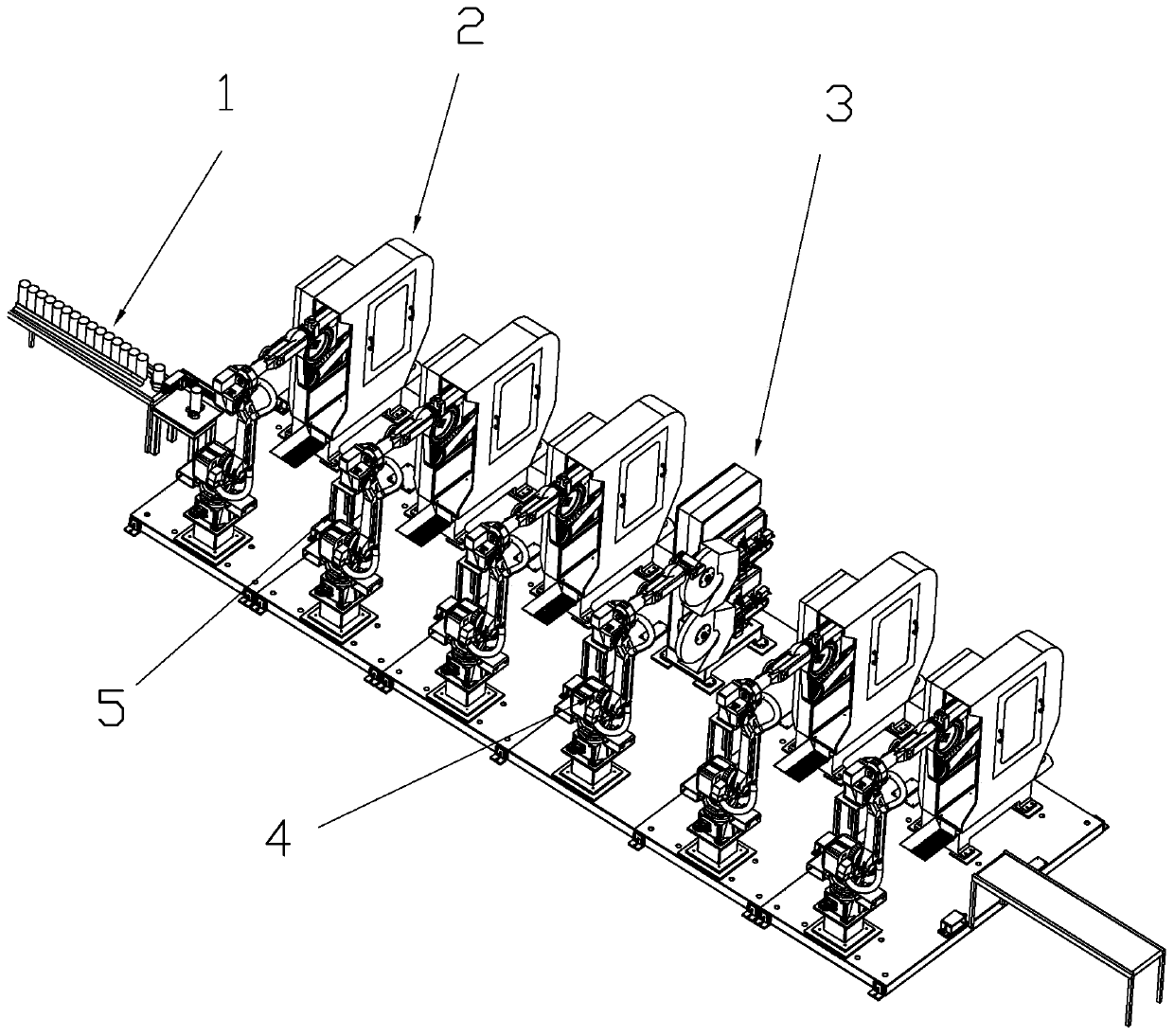
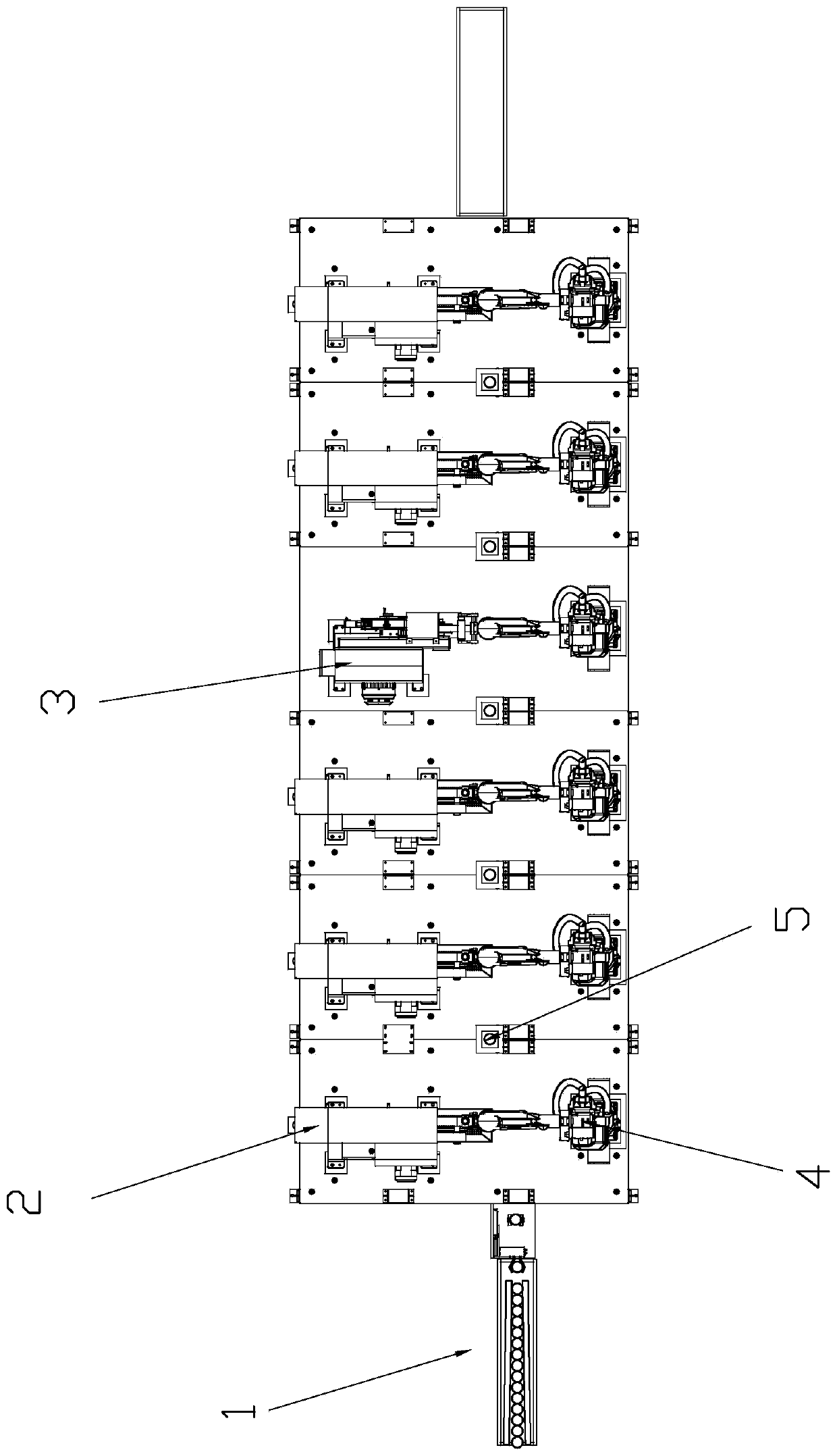
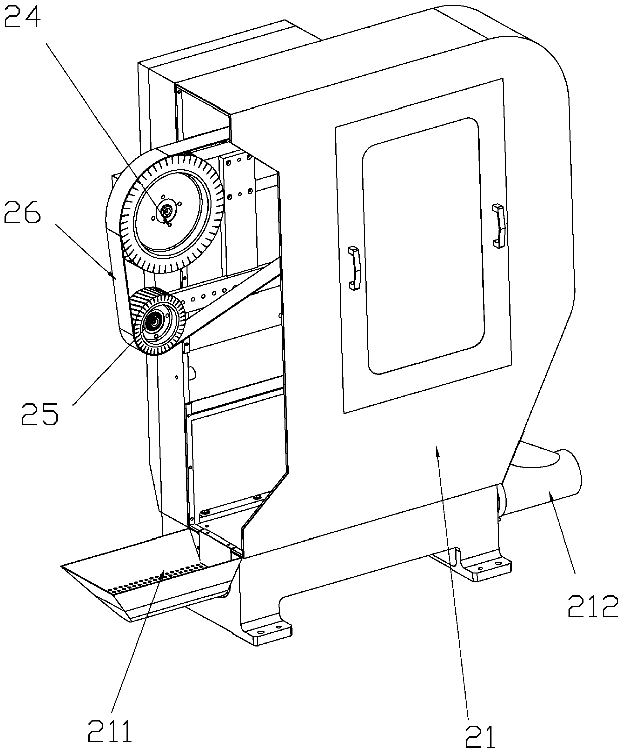
[0040] Such as Figure 1-Figure 12 As shown, a thermos cup polishing production line includes a feeding device 1, several grinding devices 2 and several polishing devices 3 arranged in sequence and used to transport thermos cups A one by one, and also includes several thermos cups A used to transfer to Grinding device 2 or polishing device 3 is an industrial robot 4 for grinding or polishing. Several grinding devices 2 and several polishing devices 3 are set in one-to-one correspondence with several industrial robots 4. The grinding device 2 includes a belt machine frame 21 The abrasive belt machine frame 21 is provided with an abrasive belt mechanism for grinding the insulation cup A. The abrasive belt mechanism includes an abrasive belt main beam 22, a drive motor 23 arranged on the abrasive belt main beam 22, and a drive wheel linked with the drive motor 23. 24. The driven wheel 25 arranged at the lower end of the driving wheel 24 and the abrasive belt 26 sleeved on the dri...


PUM


Abstract

The invention relates to a vacuum cup grinding production line. The vacuum cup grinding production line comprises a feeding device, a plurality of grinding devices and a plurality of polishing deviceswhich are sequentially arranged and used for conveying vacuum cups one by one, and further comprises a plurality of industrial robots used for transferring the vacuum cups to the grinding devices orthe polishing devices to be ground or polished. The plurality of grinding devices and the plurality of polishing devices correspond to the plurality of industrial robots in a one-to-one mode; each grinding device comprises a belt sander rack, each belt sander rack is provided with an abrasive belt mechanism, each abrasive belt mechanism comprises an abrasive belt main beam, a driving motor, a driving wheel, a driven wheel and an abrasive belt, and each driven wheel is arranged on the corresponding abrasive belt main beam through a driven support; and a floating grinding assembly is arranged between each abrasive belt main beam and the corresponding belt sander rack, each floating grinding assembly comprises a floating arm, bearing columns are arranged at the two ends of each floating arm,and each floating arm is movably connected with the corresponding abrasive belt main beam and belt sander rack through the bearing columns and enables the abrasive belt main beam to swing left and right in the belt sander rack through the corresponding floating arm.

Description

technical field [0001] The invention relates to the field of intelligent processing, in particular to a production line for grinding vacuum flasks. Background technique [0002] The stainless steel thermos cup is a cup commonly used by people for drinking water. Its stainless steel material is strong, not fragile, durable and beautiful, and is deeply loved by people. [0003] After the stamping is completed, the stainless steel cup needs to be polished. At present, in the production of stainless steel cups in China, the grinding and polishing process of the surface is usually manually operated. Manual grinding and polishing, however, has two significant technical drawbacks. One, manual grinding and polishing will waste a lot of manpower, and limited by the work experience of the operator, the quality stability of the surface grinding and polishing of the thermos cup is extremely poor. Moreover, the length and position of the burrs before different vacuum cups are differen...

Claims


Application Information

Patent Timeline
IPC IPC(8): B24B21/00B24B21/18B24B21/20B24B41/00B24B27/00B24B41/06B24B55/08
CPCB24B21/008B24B21/18B24B21/20B24B27/0069B24B41/005B24B41/06B24B55/08
Inventor 蔡曙春蔡曙鹤贺干群全阳勋张康坚林友景戴晓瑜魏人楚胡靖贺璟
Owner 浙江珂斯顿机器人科技有限公司
Why Eureka
Try Eureka