Plate feeding machine for brick machine system

A technology of loading machine and brick machine, which is applied in the field of loading machine, can solve the problems of insufficient automation of loading machine, affect the production efficiency of the brick machine system, and increase the production cost of brick making, so as to achieve compact and reasonable structural design and improve production efficiency , the effect of structural optimization

Pending Publication Date: 2020-07-10
天津市蓟州区建丰技术咨询服务部
View PDF0 Cites 2 Cited by
  • Summary
  • Abstract
  • Description
  • Claims
  • Application Information

AI Technical Summary

Problems solved by technology

[0004] The lack of automation of the existing loading machine leads to low efficiency of loading the brick supporting board (formwork), which in turn affects the production efficiency of the brick machine system
On the other hand, the continuous production method of "upper board-mold closing-vibration forming-lower board" puts forward higher requirements on the position accuracy of the upper board of the brick support board. Since the brick support board is stacked layer by layer, When loading the board, take it layer by layer from the top. If the brick supporting boards are not stacked in a regular manner, problems such as board jamming on the brick supporting board will easily occur during the subsequent boarding process.
Furthermore, the existing board loading device is easy to cause damage to the brick supporting board, resulting in the loss of the brick supporting board and increasing the production cost of brick making

Method used


Image

  • Plate feeding machine for brick machine system
  • Plate feeding machine for brick machine system
  • Plate feeding machine for brick machine system

Examples


Embodiment Construction

[0025] In order to further understand the content, features and effects of the present invention, the following examples are given in detail.

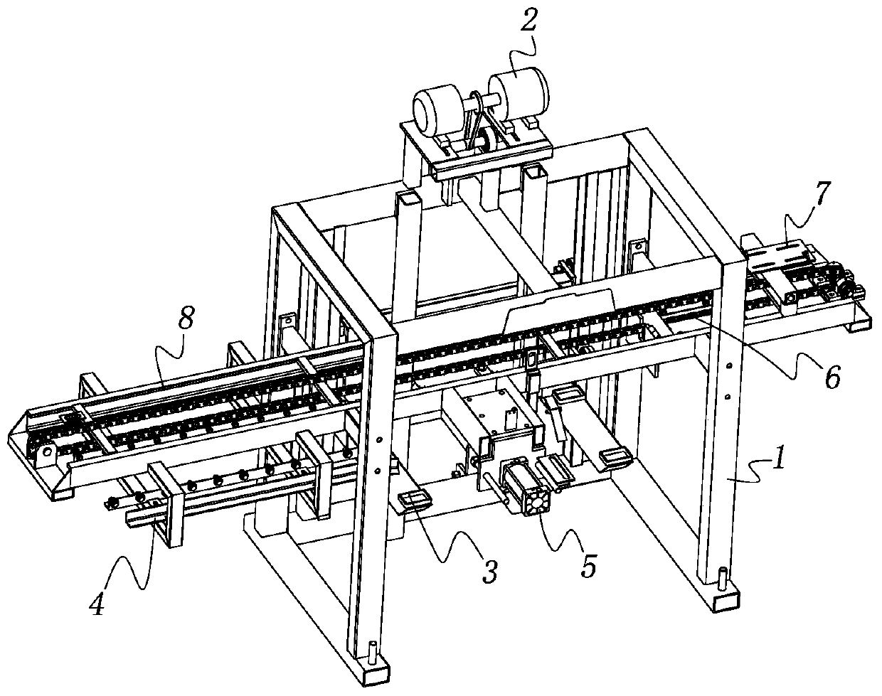
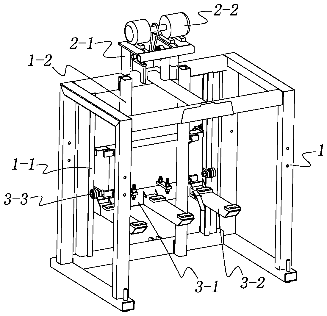
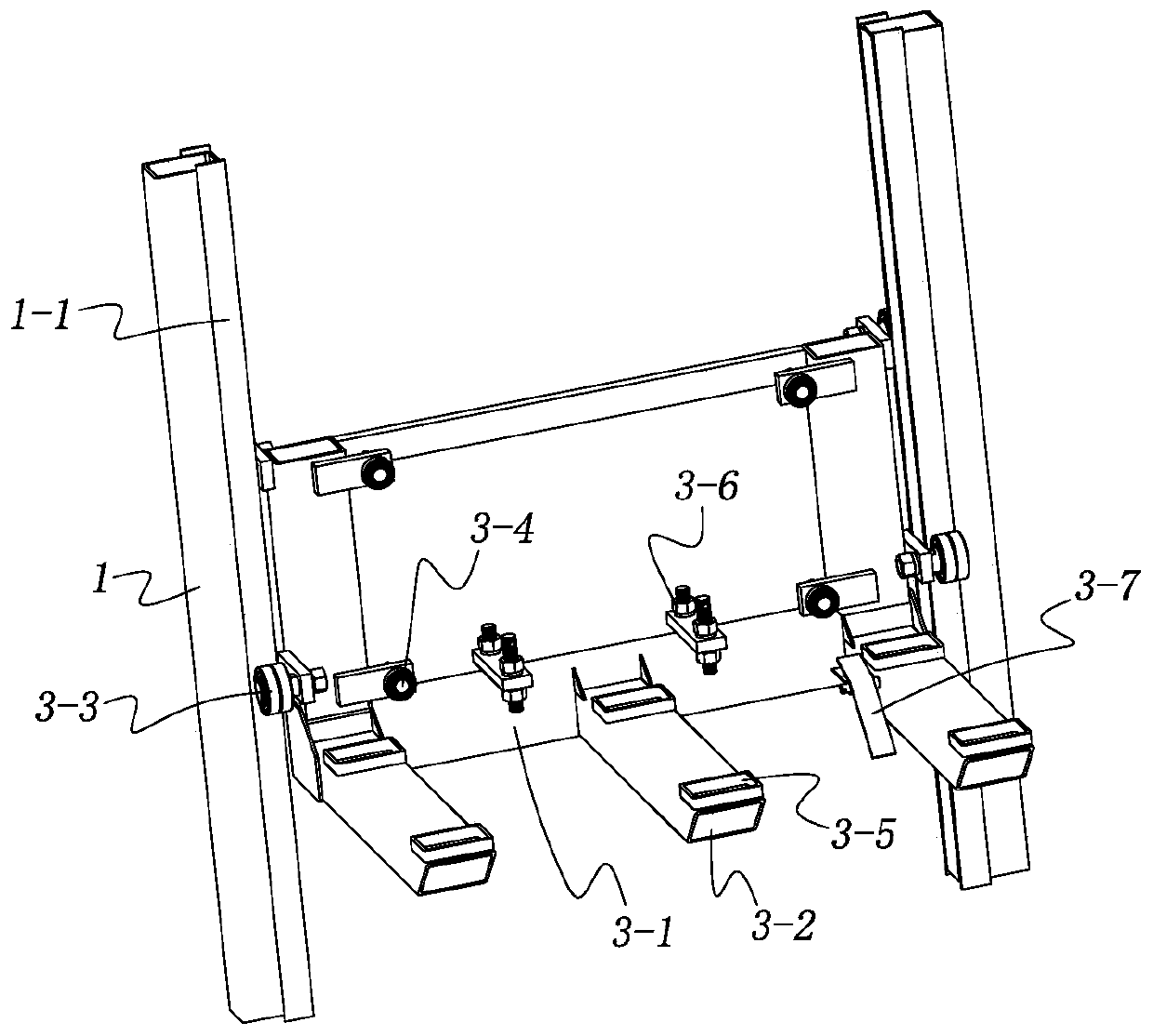
[0026] See figure 1 and figure 2 , the loading machine for the brick machine system of the present invention includes a frame 1, a frame device 8 is installed in the middle of the frame 1, a carrying device 3 is installed on the back, and a lifting drive device 2 is installed on the top, the carrying device 3 is used for The stacked multi-layer brick pallets are loaded, and the lifting drive device 2 drives the carrying device 3 to move up and down. A guide device 4, a top board device 6 and a conveying device 7 that drives the top board device 6 to move in translation are installed on the frame device 8, and an alignment device 5 is also installed at the middle part of the frame device 8, wherein the guide device 4 is used for supporting the brick board. Guided to ensure the accuracy of the moving position, the top plate device 6 p...


PUM


Abstract

The invention relates to a plate feeding machine for a brick machine system. The plate feeding machine comprises a rack, a frame device is installed in the middle of the rack, a bearing device is installed on the back of the rack, and a lifting driving device is installed on the top of the rack; a guide device, a top plate device and a conveying device are installed on the frame device, and an alignment device is further installed in the middle of the frame device; the guide device comprises an outer side hanging frame and an inner side hanging frame which are installed on the frame device, afirst limiting plate and a second limiting plate are installed between the outer side hanging frame and the inner side hanging frame, and a first rolling wheel base and a second rolling wheel base which are opposite and provided with rolling wheels are arranged between the two limiting plates; the top plate device comprises a translation frame, and a top plate is hinged to the front part of the translation frame; and the conveying device comprises a first chain wheel and a second chain wheel, a translation chain is arranged between the two chain wheels, the translation frame is fixedly connected with the translation chain, and a translation driving device for driving the translation chain is further involved. According to the plate feeding machine, the structure is compact, the plate feeding efficiency is high, the operation smoothness is high, and the damage to a brick supporting plate is small.

Description

technical field [0001] The invention belongs to the technical field of brick making equipment, and in particular relates to a plate loading machine used in a brick machine system. Background technique [0002] Unburned bricks are a kind of non-burning bricks that use fly ash, coal slag, coal gangue, tailings slag, chemical slag or natural sand, sea mud, etc. A new type of wall material has been more and more widely used due to its wide source of raw materials, energy saving and waste utilization, high strength, resistance to water, resistance to weathering, corrosion, freeze-thaw, and many other advantages, and its demand is also increasing. [0003] The process of automatic brick making and brick output of the brick machine system is: the brick supporting plate is transported to the station of the brick machine equipment by the upper plate machine, the lower mold is moved to the brick supporting plate, and the blank is injected into the downward mold. The mold is closed, a...

Claims


Application Information

Patent Timeline
IPC IPC(8): B66F7/02B66F7/28B65G59/02B28B17/00
CPCB66F7/02B66F7/28B65G59/026B28B17/00
Inventor 齐明于波
Owner 天津市蓟州区建丰技术咨询服务部
Why Eureka
Try Eureka