Light-emitting device

A technology of a light-emitting device and a wavelength conversion device, which is applied to lighting devices, light guides of lighting devices, components of lighting devices, etc., can solve the problems of low color rendering index of output light, low luminous efficiency, insufficient blue light, etc.

Active Publication Date: 2020-07-10
赫尔曼友瀚范贝赫库姆 +1
View PDF9 Cites 4 Cited by
  • Summary
  • Abstract
  • Description
  • Claims
  • Application Information

AI Technical Summary

Problems solved by technology

[0004] The technical problem to be solved by the present invention is: the luminous efficiency of the existing light-emitting devices is not high and the blue light is usually insuff

Method used


Image

  • Light-emitting device
  • Light-emitting device
  • Light-emitting device

Examples


Embodiment 1

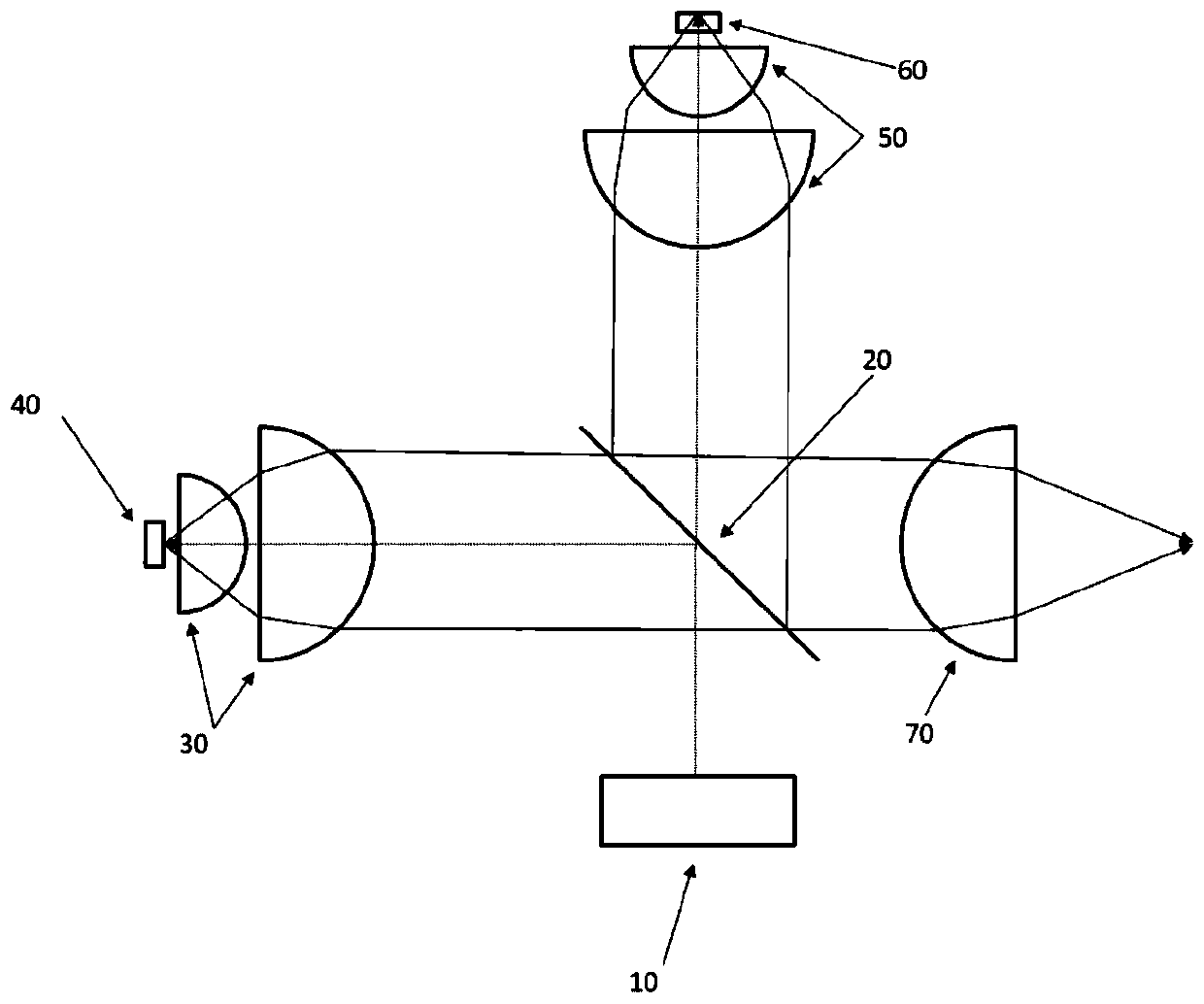
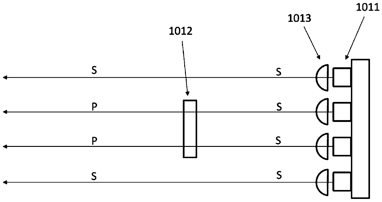
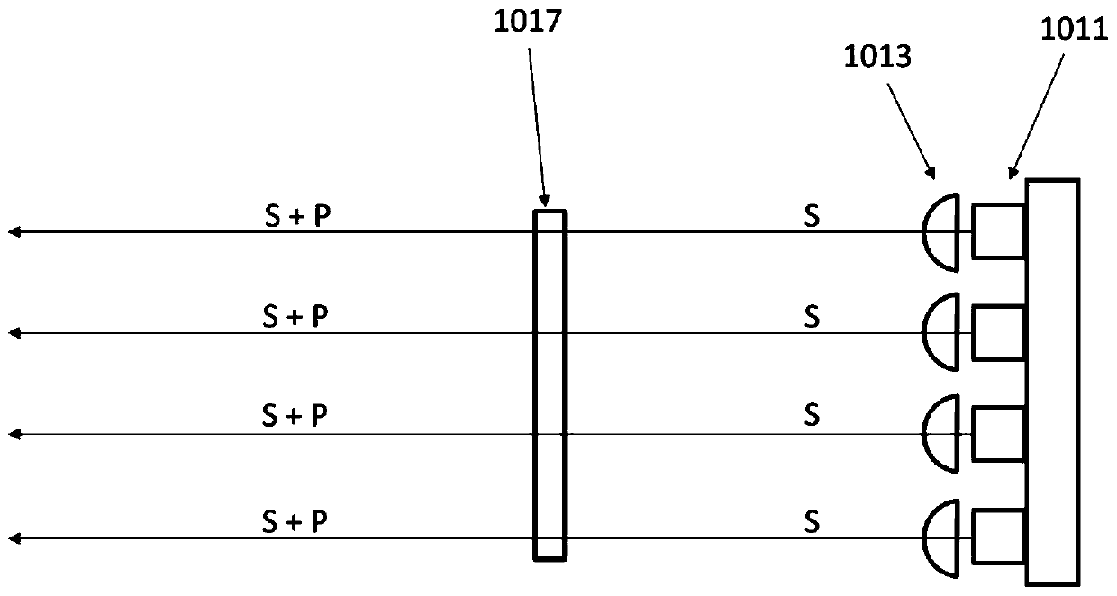
[0138] Such as Figure 10 As shown, the first laser light source 101 is provided with a blue light (central wavelength is 460nm) laser and a collimating lens, and a half-wave plate is arranged in front of some of the lasers, so the first laser light source 101 can emit nearly parallel blue light (central wavelength 460nm) and enter the polarizing beam splitter 102, and these light rays include the light of S-polarized light and P-polarized light relative to the incident plane of the polarizing beam splitter 102. Here the polarizing beam splitter 102 is selected to be a narrow-band (440-470nm) polarizing cube beam splitter. For blue light (the center wavelength is 460nm), the polarizing beam splitter 102 can reflect the S polarized light and transmit the P polarized light. For the wavelength longer than 470nm Visible light (such as green light) can be transmitted by the polarizing beam splitter 102 . The polarization beam splitter 102 transmits the P-polarized light in the inc...

Embodiment 2

[0143] Such as Figure 11 As shown, the difference between this embodiment and Embodiment 1 is that the polarizing beam splitter 102 selected in this embodiment is flat rather than cube-shaped, and it is lighter than the cube-shaped polarizing beam splitter, so that the whole device can be made Less weight. Other structures and working methods of this embodiment are the same as those of Embodiment 1.

Embodiment 3

[0145] Such as Figure 12As shown, the difference between this embodiment and Embodiment 2 is that a second wave plate 112 is used in the second optical path, because in this embodiment, the blue light in the second optical path is not completely absorbed by the first wavelength conversion device. 107 is absorbed by the wavelength conversion material, and the remaining blue light and green light are reflected back to the second light concentrating element 106 by the reflective substrate of the first wavelength conversion device 107 . The second wave plate 112 is a quarter wave plate, which can change its polarization state for blue light (center wavelength is 460nm). The blue light passes through the second wave plate 112 twice successively, and its polarization direction changes from the original S polarized light to P polarized light. Specifically, after the blue light passes through the second wave plate 112 for the first time, it changes from the original S-polarized ligh...


PUM


Abstract

The invention provides a light-emitting device which is characterized by comprising a first laser light source, a polarization beam splitter, a first wave plate, a first light condensation element, ascattering device, a second light condensation element, a first wavelength conversion device, a dichroscope, a third color light generation part and a light condensation part. The light-emitting device provided by the invention has the advantages of high brightness, small optical expansion amount, high color rendering index, uniform light spots, long service life, high efficiency and the like. Thelight-emitting device can be applied to systems requiring high illumination intensity and small optical expansion, such as entertainment lighting systems, projection systems, automobile lighting systems, medical lighting systems, searchlighting lighting systems, field operation lighting systems, navigation lighting systems, portable lighting systems and the like.

Description

technical field [0001] The invention belongs to the field of lighting, in particular to the field of solid-state light source lighting. The light-emitting device provided by the present invention can be applied to systems that require high light intensity and small etendue, such as entertainment lighting systems, projection systems, automotive lighting systems, medical lighting systems, search lighting systems, field operation lighting systems, Nautical lighting systems, portable lighting systems, etc. Background technique [0002] As an ideal point light source, laser has the advantages of small etendue, long life and no mercury. Using it as a light source to excite the fluorescent powder can produce colored light or white light, and at the same time cooperate with the use of optical elements to obtain an ideal light-emitting device with a small etendue. figure 1 It is a structural schematic diagram of a light emitting device in the prior art. Such as figure 1 As shown,...

Claims


Application Information

Patent Timeline
IPC IPC(8): G02B27/28G02B27/10G02B27/09F21S2/00F21K9/61F21K9/64F21V9/30F21K9/69F21V5/04F21V8/00F21Y115/10
CPCG02B27/283G02B27/1006G02B27/286G02B27/0938F21S2/00F21K9/61F21K9/64F21V9/30F21K9/69F21V5/04F21V2200/00F21Y2115/10
Inventor 赫尔曼·友瀚·范·贝赫库姆郑华
Owner 赫尔曼友瀚范贝赫库姆
Why Eureka
Try Eureka