A power battery tab cooling system with exhaust gas

A power battery and exhaust gas exhaust technology, which is applied to secondary batteries, exhaust plug devices, battery pack components, etc., can solve problems such as poor heat transfer, uneven flow field, and low thermal conductivity of diaphragm materials, and achieve It is convenient for long-term and safe use, improves safety and stability, and enhances the effect of heat transfer rate

Active Publication Date: 2022-07-15
HARBIN ENG UNIV
View PDF10 Cites 0 Cited by
  • Summary
  • Abstract
  • Description
  • Claims
  • Application Information

AI Technical Summary

Problems solved by technology

The air-cooled thermal management system has simple structure, small space occupation, light weight, low cost, low energy consumption, no harmful gas volume pressure, and easy maintenance, but the air thermal conductivity is low, the convective heat transfer coefficient is small, the time required for heat dissipation is long, and the Large outlet pressure difference, uneven flow field, poor temperature uniformity, high discharge rate and poor cooling effect
The liquid-cooled heat management method has large specific heat capacity, high thermal conductivity, large heat transfer coefficient, thin boundary layer, strong heat transfer capacity, integrated heat dissipation and preheating, and good temperature uniformity, but it is large in size, heavy in weight, easy to leak, and expensive High, high sealing and insulation requirements (direct liquid cooling), high energy consumption of auxiliary components, complex system
[0004] At present, the vast majority of power batteries are composed of positive electrodes, diaphragms, negative electrodes and battery casings, and the thermal conductivity of the diaphragm material is low, and the thermal resistance from the inside of the cell to the vertical surface is large, and the thermal conductivity is poor. bad

Method used


Image

  • A power battery tab cooling system with exhaust gas

Examples


Embodiment Construction

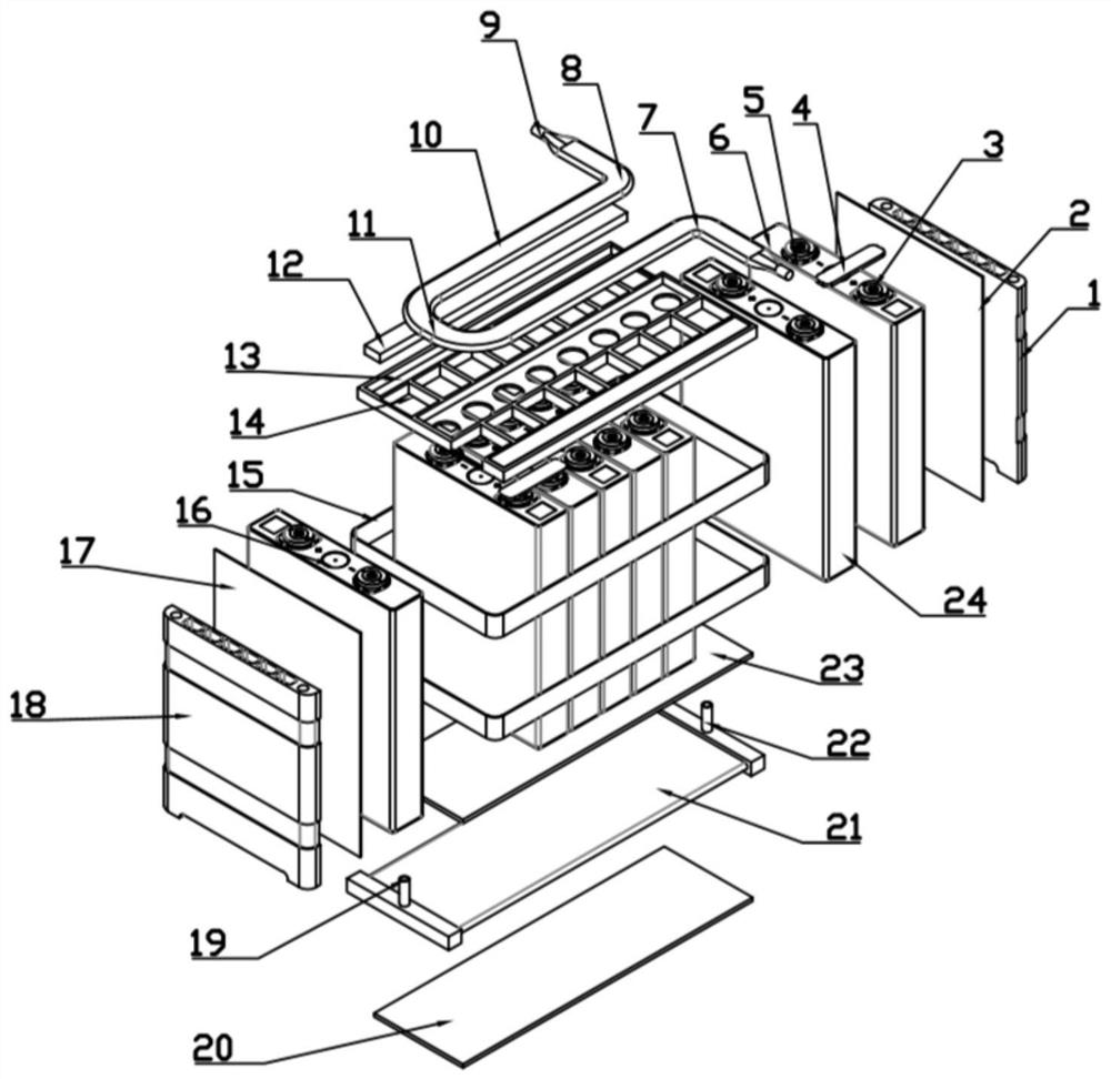
[0017] The present invention will be described in more detail below in conjunction with the accompanying drawings:

[0018] combine figure 1 , the present invention provides a power battery tab heat dissipation system that can discharge exhaust gas, without changing the original thermal management system, coupling the advantages of air-cooled and liquid-cooled thermal management methods, and effectively solves the traditional liquid-cooled thermal management method The disadvantage of not being able to discharge the exhaust gas generated in the thermal management system; at the same time, the thermal management method of heat dissipation by battery tabs can efficiently dissipate heat from the battery module and further improve the temperature uniformity of the system; the system is provided with multi-layer safety protection, It can better avoid the current frequent battery thermal runaway problem and promote the development of new energy hybrid and pure electric vehicles.

...


PUM


Abstract

The purpose of the present invention is to provide a power battery tab heat dissipation system that can discharge exhaust gas, including a battery core, a tab air cooling tube, a controller, an isolation frame, a heat soaking film, a lower liquid cooling plate, a side heat insulation plate, a bottom Insulation pads. After the cells are grouped, an isolation frame is set at the top, and a lower liquid cooling plate is set at the bottom; a pressure relief channel is set above the safety valve, and the thermal conductive glue filling groove on the isolation frame is set with thermally conductive insulating silica gel; The cooling tube, the pole ear air cooling tube and the pole ear busbar are provided with a heat soaking film; an exhaust valve is arranged on the air cooling tube, and a gas sensor is arranged in the module space. Based on the heat dissipation of the positive and negative pole lugs, the invention realizes the complementary advantages of air cooling and liquid cooling. The thermal management system has high space utilization, small heat exchange thermal resistance, and good cooling effect.

Description

technical field [0001] The invention relates to a power battery thermal management system. Background technique [0002] In recent years, accidents such as smoke, spontaneous combustion, and fire have occurred frequently in new energy vehicles. Power batteries, as their core components, are moving towards high energy density, long cruising range, short charging time, high safety, high space utilization, and light weight. The direction of development and long cycle life. [0003] In the safety accidents of new energy vehicles, thermal management problems are prominent. The air-cooled heat management system has simple structure, small footprint, light weight, low cost, low energy consumption, no harmful gas volume pressure, and easy maintenance. The outlet pressure difference is large, the flow field is uneven, the temperature uniformity is poor, and the cooling effect of high discharge rate is poor. The liquid-cooled heat management method has large specific heat capacity,...

Claims


Application Information

Patent Timeline
Patent Type & Authority Patents(China)
IPC IPC(8): H01M10/613H01M10/625H01M10/653H01M10/6561H01M10/6567H01M10/658H01M50/531
CPCH01M10/613H01M10/625H01M10/653H01M10/6561H01M10/6567H01M10/658H01M50/30Y02E60/10
Inventor 范立云李奎杰徐荣马龙冯力东尹冰倩
Owner HARBIN ENG UNIV
Why Eureka
Try Eureka