
Magnetic resonance CEST imaging frequency drift correction method and device, medium and imaging equipment

A frequency drift and correction method technology, applied in the direction of measuring devices, measuring magnetic variables, instruments, etc., can solve the problem of affecting the robustness and repeatability of magnetic resonance CEST imaging, reducing the clinical reference value of CEST images, and high fat signals in CEST images To achieve real-time correction of main magnetic field frequency drift, improve robustness and repeatability, and ensure reliability

Active Publication Date: 2020-07-14
ZHEJIANG UNIV
View PDF5 Cites 4 Cited by
  • Summary
  • Abstract
  • Description
  • Claims
  • Application Information

AI Technical Summary

Problems solved by technology

However, the MTRasym analysis method is very sensitive to the frequency drift of the main magnetic field. The frequency drift of the main magnetic field will cause the MTRasym analysis method to significantly overestimate or underestimate the CEST effect, which will affect the robustness and repeatability of magnetic resonance CEST imaging.
Although some researchers have adopted some post-processing methods to correct the frequency drift of the main magnetic field, the post-processing method cannot solve the problem of reduced fat suppression efficiency caused by the frequency of the main magnetic field, resulting in a higher fat signal in the CEST image. Reduced clinical reference value of CEST images

Method used


Image

  • Magnetic resonance CEST imaging frequency drift correction method and device, medium and imaging equipment
  • Magnetic resonance CEST imaging frequency drift correction method and device, medium and imaging equipment
  • Magnetic resonance CEST imaging frequency drift correction method and device, medium and imaging equipment

Examples


Embodiment

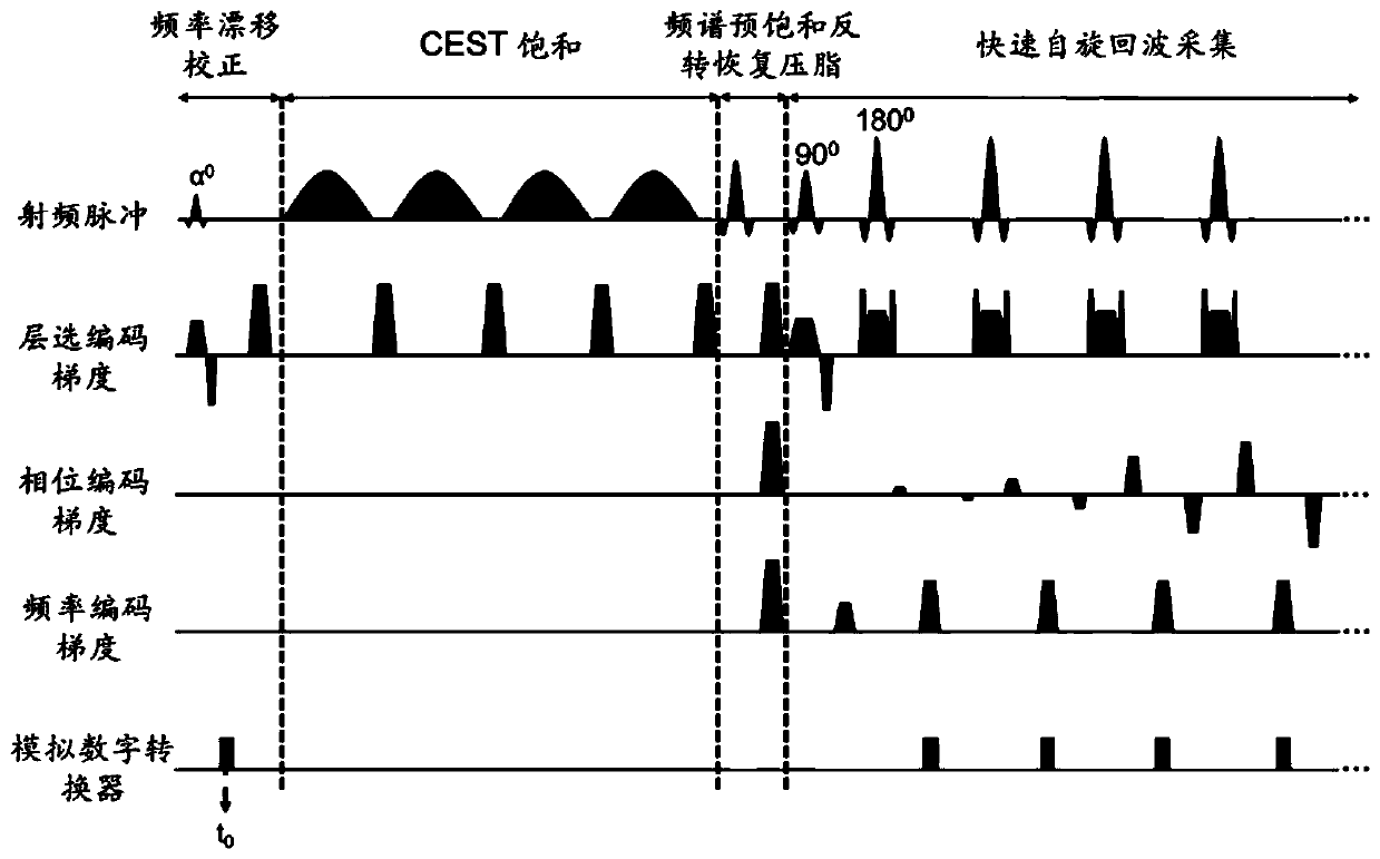
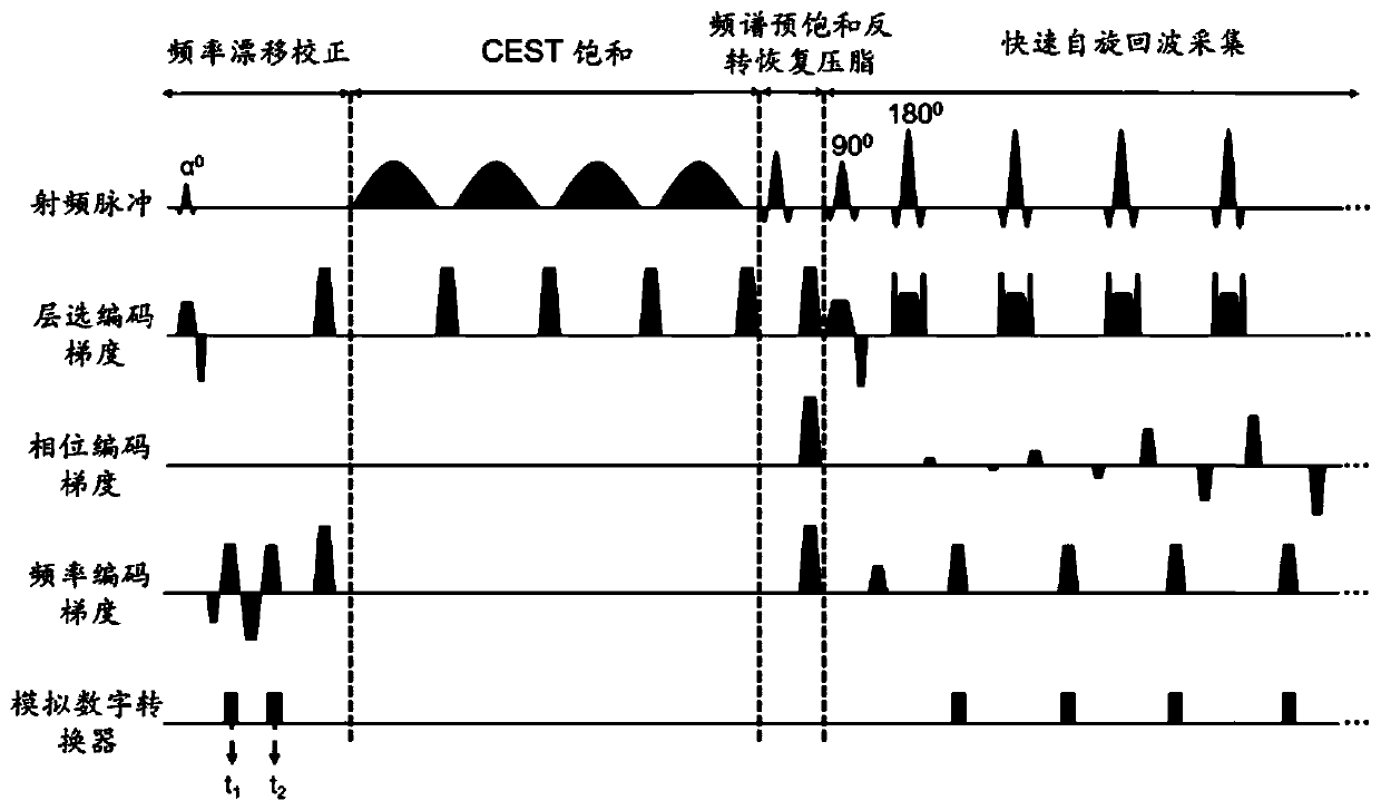
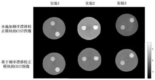
[0087] The above-mentioned magnetic resonance CEST imaging sequence based on the frequency drift correction module of collecting free induction decay signal or gradient echo signal and the conventional magnetic resonance CEST imaging sequence without frequency drift correction module were used in the water model and the brains of 15 subjects respectively. A comparative test was carried out in the magnetic resonance CEST imaging experiment. Refer to the above S1-S3 for specific methods, which will not be repeated here, and only the specific parameters here will be introduced below. In this embodiment, the target layer is excited with a radio frequency pulse with a flip angle of 3 degrees, respectively at t 0 = 6.98ms to collect single-line free induction attenuation signal (such as figure 1 shown) or at t 1 =2.52ms,t 2 =8.33ms Collect two lines of non-phase-encoded gradient echo signals at two moments (such as figure 2 ), the number of sampling points for each line of free...


PUM


Abstract

The invention discloses a magnetic resonance CEST imaging frequency drift correction method and device, a medium and imaging equipment. The method comprises the following steps of: firstly, in a frequency drift correction module, exciting a target layer by using a small-flip-angle radio frequency pulse, and acquiring a single-row free induction attenuation signal or two-row non-phase encoding gradient echo signals; secondly, according to the phase information and the acquisition time of a single-row free induction attenuation signal or two-row non-phase coding gradient echo signals, calculating main magnetic field frequency drift values respectively; adjusting the center frequency of the magnetic resonance equipment in real time according to the main magnetic field frequency drift calculation value to realize real-time correction of the main magnetic field frequency drift; carrying out CEST imaging. Aiming at the problem of main magnetic field frequency drift in magnetic resonance CESTimaging, the invention provides a frequency drift correction module for correcting frequency drift in real time based on acquisition of a free induction attenuation signal or a non-phase encoding gradient echo signal, and therefore the robustness and repeatability of magnetic resonance CEST imaging are improved.

Description

technical field [0001] The present application relates to the field of magnetic resonance technology, in particular to the field of magnetic resonance CEST imaging frequency drift correction. Background technique [0002] Magnetic resonance CEST (Chemical Exchange Saturation Transfer) imaging is a new type of molecular magnetic resonance imaging technology. Compared with conventional magnetic resonance imaging technology, this technology can indirectly detect the spatial distribution of endogenous low-concentration metabolites. Its clinical application value has been verified in various diseases. Since CEST imaging is affected by various interference effects such as direct water saturation, asymmetric magnetization analysis (Magnetization Transfer Ratio Asymmetry Analysis, MTRasym) is often used clinically to remove other interference effects to propose a pure CEST effect. However, the MTRasym analysis method is very sensitive to the frequency drift of the main magnetic fie...

Claims


Application Information

Patent Timeline
IPC IPC(8): G01R33/58
CPCG01R33/583G01R33/5605G01R33/56563G01R33/5617G01R33/5601G01R33/56572G01R33/5659
Inventor 张祎刘瑞斌张洪锡徐义程孙毅吴丹
Owner ZHEJIANG UNIV
Learn More