Secondary inversion parallel main circuit

A secondary inverter, inverter circuit technology, applied in electrical components, high-efficiency power electronic conversion, conversion of AC power input to AC power output, etc., can solve the problem of uneven current flow between two IGBTs, high heat dissipation conditions, and poor reliability. and other problems, to achieve the effect of reducing weight and volume, solving the problem of current sharing, and ensuring reliability

Inactive Publication Date: 2020-07-14
SHANGHAI HUGONG ELECTRIC WELDING MACHINE MFG
View PDF3 Cites 0 Cited by
  • Summary
  • Abstract
  • Description
  • Claims
  • Application Information

AI Technical Summary

Problems solved by technology

[0004] The above-mentioned existing technical solutions have the following defects: on the basis of the above-mentioned secondary inverter main circuit, the structure of the secondary inverter circuit of the traditional high-power inverter AC / DC arc welding power supply is relatively simple. Take the output of 600A as an example , mainly in the following structure: Option 1: such as figure 1 As shown, two high-power IGBT (Insulated Gate Bipolar Transistor, insulated gate bipolar transistor) single-tube modules of 600A / 1200V are used, with large total heat generation, high local temperature, high cost, and general reliability; scheme two: as figure 2 As shown, two high-voltage IGBT half-bridge modules of 300A / 1200V are connected in parallel, and the total calorific value is smaller than that of the scheme. Although the cost is slightly lower, the two IGBTs do not share the current, and the reliability is not as good as the scheme one; scheme three: image 3 As shown, 2 low-power IGBT half-bridge modules of 300A / 600V are connected in parallel. Compared with the first and second schemes, the heat generation is small and the cost is low, but the two IGBTs do not share the current, and the high current operation itself will produce a higher peak value. , the IGBT module has the risk of voltage breakdown, and the reliability is not as good as the second scheme
Since the IGBT will generate heat and conduction loss when it works, and the greater the operating current of the IGBT, the greater the conduction loss, and the conduction loss is proportional to the square of the operating current; the higher the IGBT frequency, the greater the turn-on and turn-off losses, and the IGBT The heat generation is serious, and the heat dissipation conditions are higher; and the high current operation is often accompanied by a relatively high reverse peak voltage, which requires a higher withstand voltage and a higher price IGBT module. Generally speaking, it requires higher cost, making the whole machine weakened market competitiveness

Method used


Image

  • Secondary inversion parallel main circuit
  • Secondary inversion parallel main circuit
  • Secondary inversion parallel main circuit

Examples


Embodiment Construction

[0030] The present invention will be described in further detail below in conjunction with the accompanying drawings.

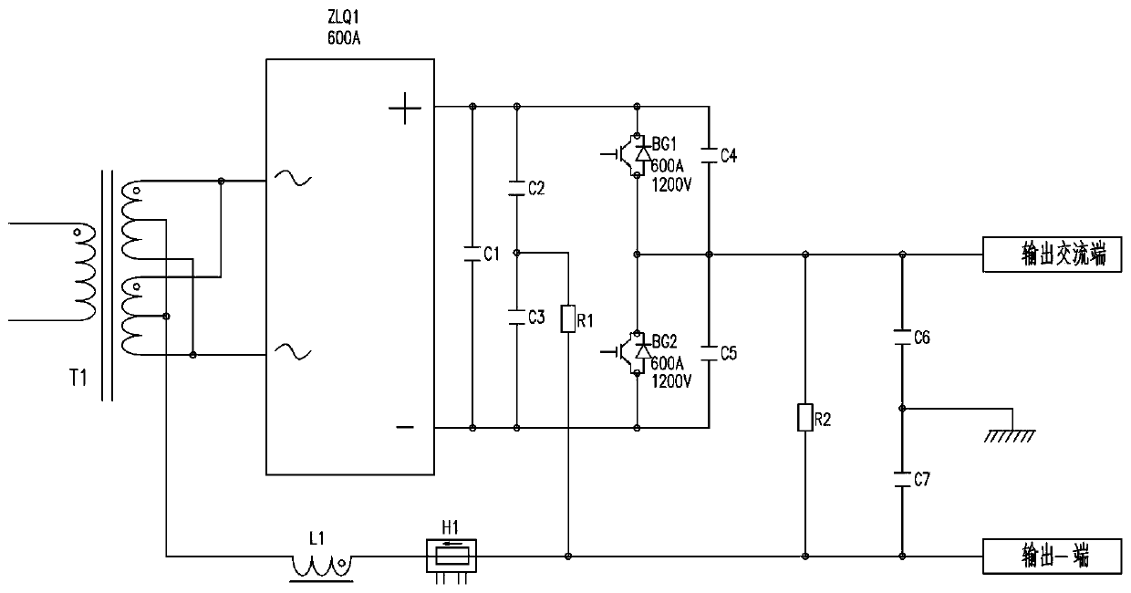
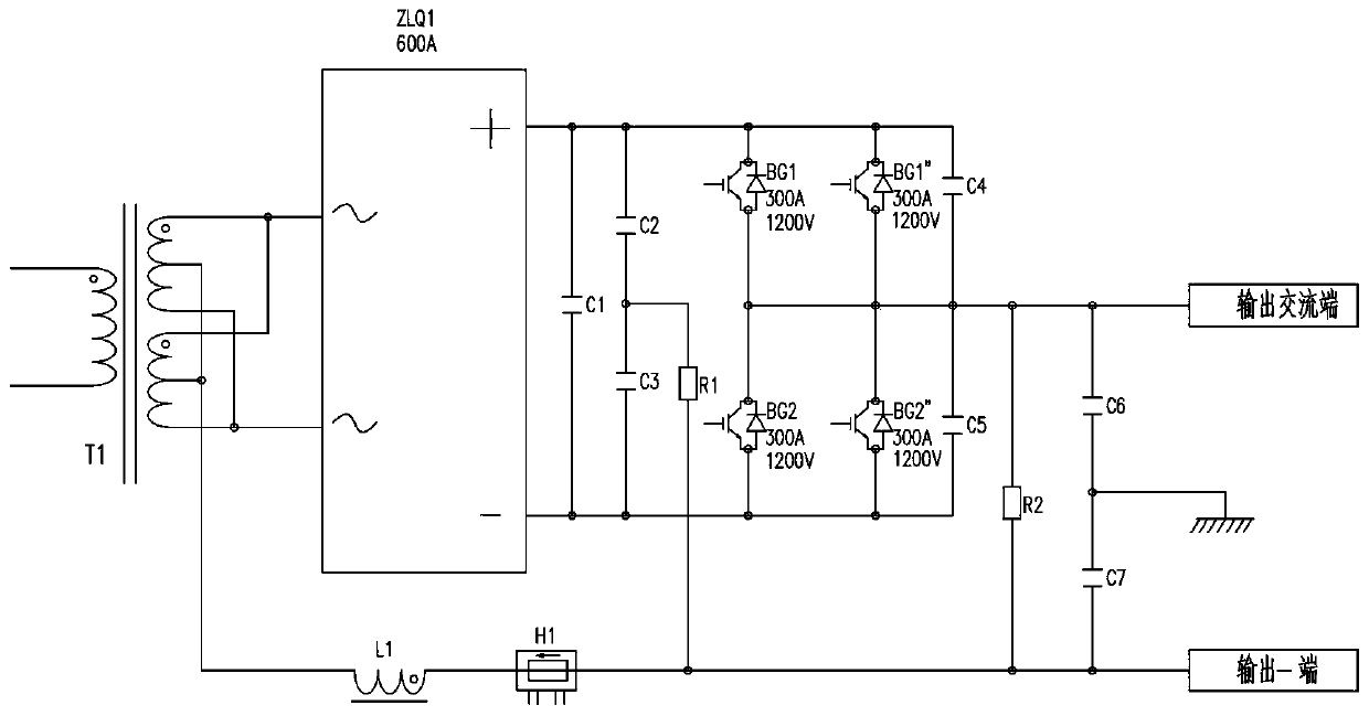
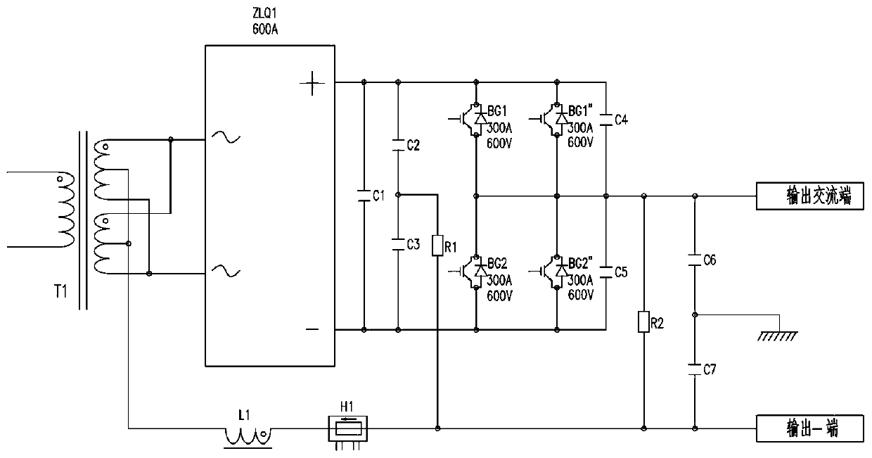
[0031] refer to Figure 4 , is a secondary inverter parallel main circuit disclosed in the present invention, including a main transformer T1, the main transformer T1 includes a first side winding and a second side winding, and the first side winding is connected to the first and second side windings. Secondary inverter circuit, the second secondary side winding is connected to the second secondary inverter circuit, the center tap of the first side winding and the center tap of the second secondary side winding are interleaved through the magnetic ring L2 and then connected as The output negative terminal of the secondary inverter parallel main circuit, the output terminal of the first secondary inverter circuit is connected to the output terminal of the second secondary inverter circuit and serves as the secondary inverter parallel main circuit output AC te...


PUM


Abstract

The invention relates to a secondary inversion parallel main circuit. The circuit comprises a main transformer T1, and the main transformer T1 comprises a first secondary side winding and a second secondary side winding. The first secondary side winding is connected with a first secondary inverter circuit; the second secondary side winding is connected with a second secondary inverter circuit; a center tap of the first secondary winding and a center tap of the second secondary winding penetrate through the magnetic ring L2 in a staggered manner, then are connected with each other and serve asan output negative end of the secondary inversion parallel main circuit; the output end of the first secondary inverter circuit is connected with the output end of the second secondary inverter circuit and serves as the output alternating current end of the secondary inverter parallel main circuit. According to the invention, a current-sharing inductance wiring method that the main transformers T1with the same iron core and two groups of identical secondary sides and the two center taps of the two groups of identical secondary sides penetrate through the magnetic ring in a staggered manner and magnetic circuits are mutually counteracted is adopted, so the current and voltage waveforms of the upper and lower groups of secondary sides are completely consistent.

Description

technical field [0001] The invention relates to the technical field of inverter welding power supply control, in particular to a secondary inverter parallel main circuit. Background technique [0002] With the rapid development of inverter AC and DC arc welding power sources, the market competition is becoming more and more fierce, and users have higher and higher requirements for the price, performance and reliability of arc welding power sources. Lower, better performance, higher reliability, and the most comfortable inverter AC / DC arc welding power supply. [0003] The Chinese patent with authorized announcement number CN100398245C discloses a secondary inverter main circuit of an arc welding machine, which includes a half-bridge inverter circuit, a high-voltage pre-charging circuit The charging circuit provides high voltage to the half-bridge inverter circuit, and the commutation circuit provides a freewheeling path when the current of the half-bridge inverter circuit c...

Claims


Application Information

Patent Timeline
Patent Type & Authority Applications(China)
IPC IPC(8): H02M7/5387H02M5/458H02M1/32
CPCH02M1/32H02M5/458H02M7/5387H02M1/0048Y02B70/10
Inventor 不公告发明人
Owner SHANGHAI HUGONG ELECTRIC WELDING MACHINE MFG
Why Eureka
Try Eureka