Camera assembly, camera module and mobile terminal

A camera component and image-side technology, applied in electrical components, optical components, image communication, etc.

Active Publication Date: 2020-07-17
JIANGXI JINGCHAO OPTICAL CO LTD
View PDF5 Cites 0 Cited by
  • Summary
  • Abstract
  • Description
  • Claims
  • Application Information

AI Technical Summary

Problems solved by technology

[0004] Based on this, it is necessary to provide a camera assembly, a camera module and a mobile terminal aiming at how to realize a large imaging area and reduce system sensitivity.

Method used


Image

  • Camera assembly, camera module and mobile terminal
  • Camera assembly, camera module and mobile terminal
  • Camera assembly, camera module and mobile terminal

Examples


no. 1 example

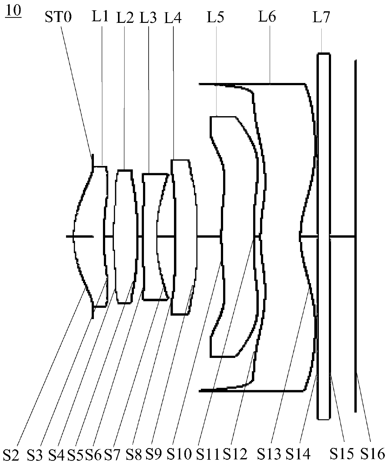
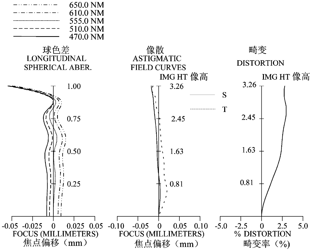
[0086] Such as figure 1 In the shown first embodiment, the camera assembly 10 sequentially includes a stop ST0, a first lens L1, a second lens L2, a third lens L3, a fourth lens L4, a fifth lens L5 and a first lens L4 from the object side to the image side. Six lenses L6. figure 2 It is the spherical chromatic aberration diagram (mm), astigmatism diagram (mm) and distortion diagram (%) of the camera assembly 10 in the first embodiment.

[0087] Wherein, the object side S2 of the first lens L1 is convex at the optical axis, the image side S3 of the first lens L1 is concave at the optical axis; the object side S2 of the first lens L1 is convex at the circumference, and the first lens L1 The image side S3 is convex at the circumference. The object side S4 of the second lens L2 is a convex surface at the optical axis, and the image side S5 of the second lens L2 is a convex surface at the optical axis; the object side S4 of the second lens L2 is a convex surface at the circumfer...

no. 2 example

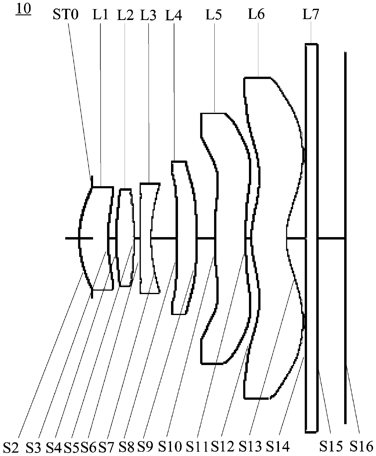
[0126] Such as image 3 In the shown second embodiment, the camera assembly 10 includes a diaphragm ST0, a first lens L1, a second lens L2, a third lens L3, a fourth lens L4, a fifth lens L5, and a first lens L4 from the object side to the image side. Six lenses L6. Figure 4 It is the spherical aberration diagram (mm), astigmatism diagram (mm) and distortion diagram (%) of the camera assembly 10 in the second embodiment.

[0127] Wherein, the object side S2 of the first lens L1 is convex at the optical axis, the image side S3 of the first lens L1 is concave at the optical axis; the object side S2 of the first lens L1 is convex at the circumference, and the first lens L1 The image side S3 is concave at the circumference. The object side S4 of the second lens L2 is a convex surface at the optical axis, and the image side S5 of the second lens L2 is a convex surface at the optical axis; the object side S4 of the second lens L2 is a convex surface at the circumference, and the ...

no. 3 example

[0140] Such as Figure 5 In the third embodiment shown, the camera assembly 10 sequentially includes a stop ST0, a first lens L1, a second lens L2, a third lens L3, a fourth lens L4, a fifth lens L5 and a first lens L4 from the object side to the image side. Six lenses L6. Figure 6 It is the spherical aberration diagram (mm), astigmatism diagram (mm) and distortion diagram (%) of the camera assembly 10 in the third embodiment.

[0141] Wherein, the object side S2 of the first lens L1 is convex at the optical axis, the image side S3 of the first lens L1 is concave at the optical axis; the object side S2 of the first lens L1 is convex at the circumference, and the first lens L1 The image side S3 is concave at the circumference. The object side S4 of the second lens L2 is a convex surface at the optical axis, and the image side S5 of the second lens L2 is a convex surface at the optical axis; the object side S4 of the second lens L2 is a convex surface at the circumference, an...


PUM


Abstract

The invention relates to a camera assembly, a camera module and a mobile terminal. The camera assembly includes, in order from an object side to an image side: a diaphragm; a first lens has positive refractive power, wherein the object side surface of the first lens is a convex surface at the optical axis, and the image side surface of the first lens is a concave surface at the optical axis; a second lens with positive refractive power, wherein both the object-side surface and the image-side surface of the second lens are convex at the optical axis; a third lens with negative refractive power;a fourth lens with positive refractive power having a convex image-side surface at the optical axis; a fifth lens with refractive power; a sixth lens that has negative refractive power, the object side surface of the sixth lens is a convex surface at the optical axis, the image side surface of the sixth lens is a concave surface at the optical axis, the object side surface and the image side surface of the sixth lens are aspheric surfaces, and at least one inflection point is arranged on the object side surface and the image side surface of the sixth lens. When the ranges of ImgH * tan (HFOV)/f and R41/OAL are satisfied, the camera assembly has a large imaging area and low sensitivity.

Description

technical field [0001] The invention relates to the field of photography and imaging, in particular to a camera assembly, a camera module and a mobile terminal. Background technique [0002] In recent years, with the rise of electronic products with photographic functions, the requirements for the imaging quality of the lens have become more and more stringent. The photosensitive element of the general optical system is nothing more than a photosensitive coupling device (Charge Coupled Device, CCD) or a complementary metal oxide semiconductor element (Complementary Metal-Oxide Semiconductor Sensor, CMOSSensor), and the pixel size of the electronic photosensitive element is limited Due to the development of semiconductor manufacturing process, in order to have higher pixels, the chip generally adopts a larger size, so a camera lens with a large imaging area is required to match the chip and improve the imaging quality. [0003] In addition, traditional optical systems mounte...

Claims


Application Information

Patent Timeline
Patent Type & Authority Applications(China)
IPC IPC(8): G02B13/00H04N5/225
CPCG02B13/0045H04N23/55H04N23/57
Inventor 邹海荣刘彬彬谢晗
Owner JIANGXI JINGCHAO OPTICAL CO LTD
Why Eureka
Try Eureka