Light field display method and system, storage medium and display panel

A display method and light field technology, which can be used in image data processing, instruments, calculations, etc., can solve problems such as low efficiency and large amount of calculation, and achieve the effect of improving efficiency and reducing the amount of calculation.

Active Publication Date: 2020-07-17
BOE TECH GRP CO LTD
View PDF16 Cites 5 Cited by
  • Summary
  • Abstract
  • Description
  • Claims
  • Application Information

AI Technical Summary

Problems solved by technology

[0005] The present invention aims at the problems of large amount of calculation and low efficiency in the existing method for generating micro-unit array images, and provides a light field display method and system, storage medium and display panel

Method used


Image

  • Light field display method and system, storage medium and display panel
  • Light field display method and system, storage medium and display panel
  • Light field display method and system, storage medium and display panel

Examples


Embodiment 1

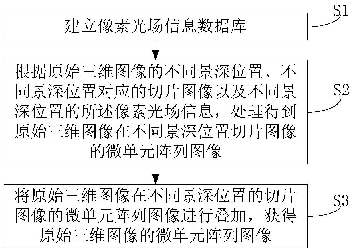
[0092] This embodiment provides a light field display method, such as figure 1 shown, including:

[0093] Step S1: Establish a pixel light field information database.

[0094] Step S2: According to the different depth-of-field positions of the original 3D image, the slice images corresponding to the different depth-of-field positions, and the pixel light field information at different depth-of-field positions, process and obtain the micro-unit array image of the sliced ​​images of the original 3D image at different depth-of-field positions;

[0095] Step S3: superimposing the micro-cell array images of sliced ​​images of the original 3D image at different depths of field to obtain the micro-cell array images of the original 3D image.

[0096] In the light field display method, the pixel light field information database is established through calculation, and after the pixel light field information database is established, the subsequent processing obtains the micro-unit array...

Embodiment 2

[0098] This embodiment provides a light field display method, including:

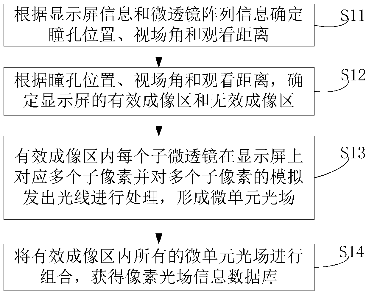
[0099] Step S1: Establish a pixel light field information database.

[0100] This step specifically includes: figure 2 as shown,

[0101] Step S11: Determine the pupil position, field angle and viewing distance according to the display screen information and the microlens array information. The microlens array includes a plurality of sub-microlenses arranged in an array; the display screen includes a plurality of sub-pixels arranged in an array.

[0102] Wherein, the lens array is located on the display side of the display screen; the display screen information includes the size of the display screen and the size of the sub-pixels on the display screen; the microlens array information includes the shape of the sub-microlens, the radial size of the sub-microlens, the sub-microlens The focal length of the sub-microlens, the radius of curvature of the sub-microlens, the refractive index of the sub-micr...

Embodiment 3

[0158] Before the object point information on the original three-dimensional image with different depth of field images is simulated to light up the sub-pixels of the display screen to generate a micro-unit array image corresponding to the slice image of the depth of field position, the image of the depth of field position of the original three-dimensional image is denoised. In this embodiment, the computer-generated slice images at different depth positions are taken as an example to obtain the original three-dimensional image. The step of obtaining the micro-cell array image of the original three-dimensional image by calculating the slice image including noise reduction of the slice image specifically includes: Figure 11 as shown,

[0159] For slice images of n different depth-of-field positions of the original three-dimensional image, noise reduction processing is performed on the slice image n: successively determine whether the gray scale value of each sub-pixel of the s...


PUM


Abstract

The invention provides a light field display method and system, a storage medium and a display panel. The light field display method comprises the following steps: establishing a pixel light field information database; according to different depth-of-field positions of an original three-dimensional image, slice images corresponding to the different depth-of-field positions and the pixel light field information of the different depth-of-field positions, processing to obtain micro-unit array images of the slice images of the original three-dimensional image at the different depth-of-field positions; and superposing the micro-unit array images of the slice images of the original three-dimensional image at the different depth-of-field positions to obtain the micro-unit array image of the original three-dimensional image. According to the light field display method, a calculation amount of obtaining the micro-unit array image of the original three-dimensional image can be reduced, and efficiency of obtaining the micro-unit array image of the original three-dimensional image is improved.

Description

technical field [0001] The invention belongs to the field of display technology, and in particular relates to a light field display method and system, a storage medium and a display panel. Background technique [0002] In the real world, the objects seen by the human eye are three-dimensional, while the traditional display only presents a two-dimensional picture without depth information. The three-dimensional display technology can present the depth information of the object, can more truly reflect the real object, and enhance the visual experience. There are many technologies capable of realizing 3D stereoscopic display, such as parallax barrier display, volumetric three-dimensional display, holographic display, light field display and so on. Parallax barrier 3D display, due to the conflict between monocular focus and binocular convergence, will cause dizziness when watching for a long time; light field display 3D display technology, monocular focus and binocular converge...

Claims


Application Information

Patent Timeline
Patent Type & Authority Applications(China)
IPC IPC(8): G02B30/52G02B30/27G06T7/557G06T7/593
CPCG06T7/557G06T7/596H04N13/307H04N13/128H04N13/305H04N13/383H04N13/122
Inventor 张庆训高健马森朱劲野
Owner BOE TECH GRP CO LTD
Why Eureka
Try Eureka