
Micro electric spark pulse power supply based on Boost and RC circuits

A technology of pulse power supply and electric spark, which is applied in the direction of circuits, energy storage components to generate pulses, electric pulse generator circuits, etc., can solve the problems of uncontrollable energy and low processing efficiency, and achieve improved energy efficiency, easy high-frequency discharge, The effect of small discharge energy

Pending Publication Date: 2020-07-17
NANJING UNIV OF SCI & TECH
View PDF2 Cites 0 Cited by
  • Summary
  • Abstract
  • Description
  • Claims
  • Application Information

AI Technical Summary

Problems solved by technology

The high requirement for machining accuracy means that the energy of a single discharge of the pulse power supply must be small enough, and the energy can be fine-tuned. However, most of the micro-EDM pulse power supplies on the market currently use a relaxation topology, and its single discharge energy is small, suitable for Suitable for micro-processing, but the energy is uncontrollable and the processing efficiency is low

Method used


Image

  • Micro electric spark pulse power supply based on Boost and RC circuits
  • Micro electric spark pulse power supply based on Boost and RC circuits
  • Micro electric spark pulse power supply based on Boost and RC circuits

Examples


Embodiment Construction

[0023] The solutions of the present invention will be further described below in conjunction with the accompanying drawings and specific embodiments.

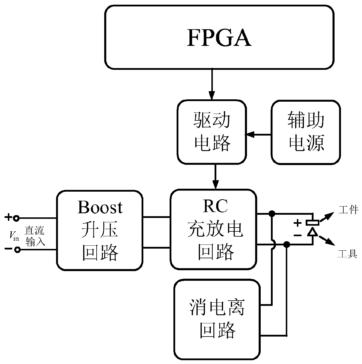
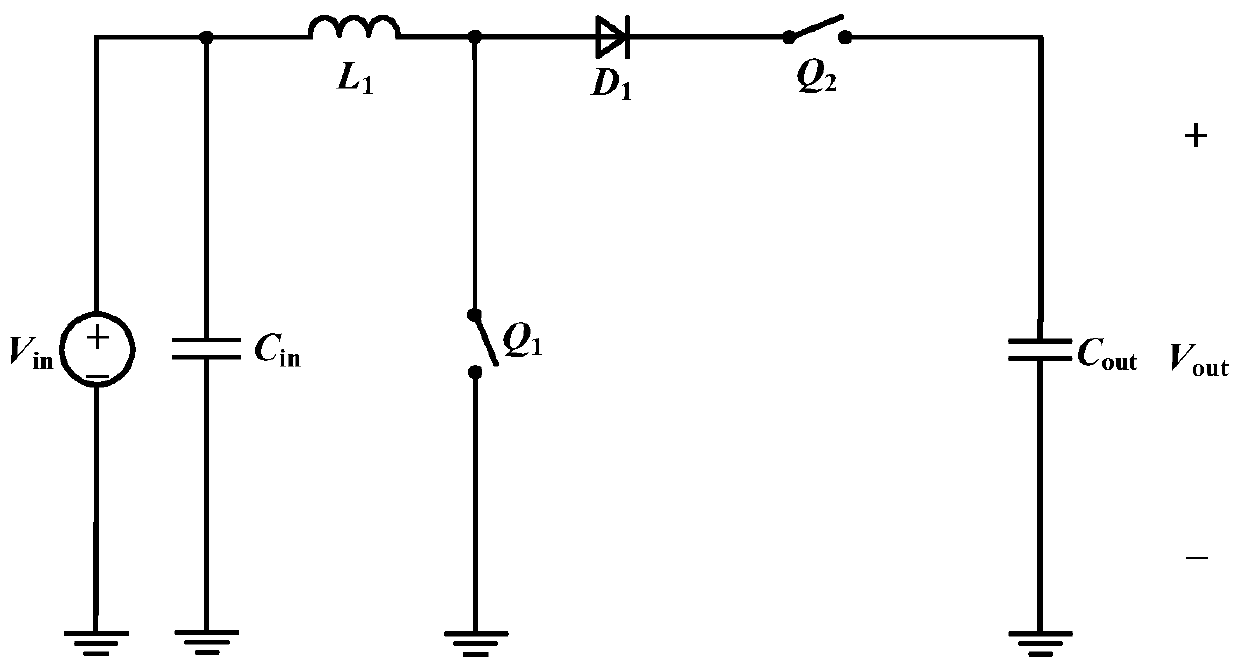
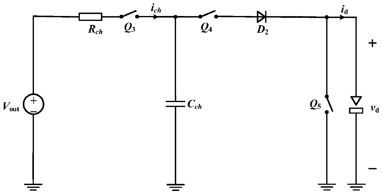
[0024] Such as figure 1 As shown, a micro-spark pulse power supply based on Boost and RC circuits includes a main power loop, a drive circuit, an auxiliary DC voltage source, and an FPGA controller. The main power loop includes a boost charging circuit and a discharging loop, wherein the boost The charging circuit adopts a Boost circuit, which is used to adjust the voltage provided by the auxiliary DC voltage source to charge the discharge circuit; the discharge circuit adopts an RC circuit to provide the gap with a breakdown voltage and discharge energy after breakdown; the auxiliary DC voltage source It is used to supply power to the main power loop and the drive circuit; the FPGA controller is used to output PWM control signals to the drive circuit according to the given target parameters; the drive circuit digitally isolate...


PUM


Abstract

The invention discloses a micro electric spark pulse power supply based on Boost and RC circuits. The micro electric spark pulse power supply is characterized by comprising a main power loop, a driving circuit, an auxiliary direct-current voltage source and an FPGA controller, wherein the main power loop comprises a boost charging circuit and a discharging loop, and the boost charging circuit adopts a Boost circuit and is used for adjusting the voltage provided by the auxiliary direct-current voltage source and charging the discharging loop, and the discharge loop adopts an RC circuit for providing the breakdown voltage and the discharge energy after breakdown for a gap; the auxiliary direct-current voltage source is used for supplying power to the main power loop and the driving circuit,the FPGA controller is used for outputting a PWM control signal to the driving circuit according to a given target parameter, and the driving circuit performs digital isolation and amplification on the PWM control signal, and generates a driving signal to drive a switching tube in the main power loop to be switched on and switched off. According to the present invention, the charging voltage controllability and the energy adjusting precision are improved, and the machining precision and the machining quality are improved.

Description

technical field [0001] The invention relates to a high-frequency pulse power supply, in particular to a micro spark pulse power supply based on Boost and RC circuits. Background technique [0002] The pulse power supply is a core part of the EDM machine tool. The design of the pulse power supply has an important impact on the roughness of the machined surface, the damage degree of the tool electrode, the machining accuracy, the machining efficiency and the utilization rate of electric energy. The high requirement for machining accuracy means that the energy of a single discharge of the pulse power supply must be small enough, and the energy can be fine-tuned. However, most of the micro-EDM pulse power supplies on the market currently use a relaxation topology, and its single discharge energy is small, suitable for It is suitable for micro-processing, but the energy is uncontrollable and the processing efficiency is low. Contents of the invention [0003] The purpose of th...

Claims


Application Information

Patent Timeline
IPC IPC(8): H02M9/04H02M3/158H02M3/157B23H1/02H03K3/57
CPCH02M11/00H02M3/158H02M3/157B23H1/02H03K3/57
Inventor 杨飞邵佳钰汪志鹏史顺飞吴鹏程覃德凡王一娉李宏良方斌
Owner NANJING UNIV OF SCI & TECH
Learn More