
Sensorless model prediction flux linkage control method for permanent magnet synchronous motor

A technology of permanent magnet synchronous motor and sensor model, which is used in motor control, motor generator control, electronic commutation motor control, etc., and can solve the problems of large torque ripple, poor robustness, and poor dynamic effect.

Pending Publication Date: 2020-07-17
NANTONG UNIVERSITY
View PDF0 Cites 10 Cited by
  • Summary
  • Abstract
  • Description
  • Claims
  • Application Information

AI Technical Summary

Problems solved by technology

The sliding mode observer algorithm is one of the latter. This algorithm has a simple structure, strong robustness, and fast dynamic response, but it also has filtering difficulties, large error in rotor position angle estimation, estimated value lags behind the actual value, and poor low-speed performance. question
[0003] In addition, for the position sensorless control technology of permanent magnet synchronous motor, researchers have conducted extensive research based on various control technologies, such as vector control, direct torque control, sliding mode control and fuzzy control, etc. There are certain deficiencies in both, such as large torque ripple, poor robustness, poor dynamic effect, complex algorithm, etc.

Method used


Image

  • Sensorless model prediction flux linkage control method for permanent magnet synchronous motor
  • Sensorless model prediction flux linkage control method for permanent magnet synchronous motor
  • Sensorless model prediction flux linkage control method for permanent magnet synchronous motor

Examples


Embodiment Construction

[0035] The present invention will be further described in detail below in conjunction with the accompanying drawings and examples. The following examples are explanations of the present invention and the present invention is not limited to the following examples.

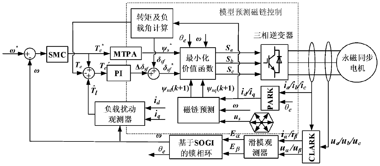
[0036] like figure 1 As shown, the present invention provides a sensorless model predictive flux linkage control method for a permanent magnet synchronous motor, comprising the following steps:

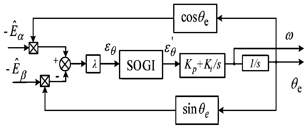
[0037] S1. Sampling three-phase current i a / i b / i c and voltage u a / u b / u c , after CLARK and PARK coordinate transformation, the αβ axis current i is obtained α / i βand αβ axis voltage u α / u β , and the dq axis current i d / i q , the αβ axis current i α / i β and αβ axis voltage u α / u β Substituting the sliding mode observer to estimate the extended back electromotive force E α and E β ;

[0038] Specifically, in the present invention, the extended counter electromotive force E α and E β The estima...


PUM


Abstract

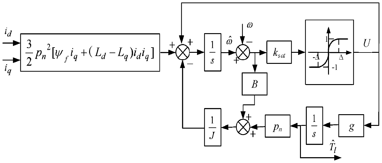
The invention belongs to the field of electromechanical control, and discloses a sensorless model prediction flux linkage control method for a permanent magnet synchronous motor. The method comprisesthe following steps: firstly, observing a motor rotating speed omega and a rotor position angle theta e through a sliding mode observer and a phase-locked loop based on SOGI; then, making the given rotating speed omega* and the rotating speed omega pass through a rotating speed loop SMC controller to obtain a given torque Te*; then, observing a load disturbance value according to the rotating speed omega and d / q axis current id / iq, and compensating the load disturbance value to the given torque Te* in a feedforward manner; and finally, substituting the observed rotating speed omega, the rotorposition angle theta e, the given torque Te*, the load disturbance value, the sampled three-phase voltage ua / ub / uc, the three-phase current ia / ib / ic and the like into a model prediction flux linkage control module for operation. According to the method, by adopting the mode of the sliding mode observer and the improved phase-locked loop, the rotor position estimation precision is improved; based on model prediction flux linkage control, setting of current loop parameters and weight coefficients is not needed; and sliding mode control and the load disturbance observer are combined, so that thesystem robustness and the anti-interference capacity are improved.

Description

technical field [0001] The invention relates to the field of electromechanical control, in particular to a sensorless model predictive flux linkage control method for a permanent magnet synchronous motor. Background technique [0002] The position sensorless control technology of the permanent magnet synchronous motor uses the relevant electrical signals in the winding to estimate the rotor position and speed, thus eliminating the mechanical sensor, reducing the size and cost of the motor, and increasing the reliability of the system. Current position estimation algorithms can be divided into two types based on signal injection and observers. The former uses the saliency of the motor to estimate the rotor position, but continuous injection of excitation signals requires complex signal processing, resulting in low inverter voltage utilization and slow dynamic response. The latter relies on the back electromotive force in the dynamic model to estimate the speed, which is easy...

Claims


Application Information

Patent Timeline
IPC IPC(8): H02P21/28H02P21/18H02P21/13H02P21/00H02P6/182H02P6/10
CPCH02P21/28H02P21/18H02P21/13H02P21/0007H02P6/182H02P6/10H02P2203/03
Inventor 张蔚翟良冠王家乐金鑫杨泽贤
Owner NANTONG UNIVERSITY
Learn More