
3D-printed high-sensitivity magnetic field sensor adopting two-photon femtosecond laser direct writing technology for and manufacturing method thereof

A magnetic field sensor and femtosecond laser technology, applied in the field of optical sensing, can solve the problems of poor corrosion resistance of optical fiber materials, low sensitivity and stability, limited interaction space, etc., achieve high resolution, improve sensitivity and stability, easy processing effect

Pending Publication Date: 2020-07-24
ZHEJIANG UNIV
View PDF0 Cites 6 Cited by
  • Summary
  • Abstract
  • Description
  • Claims
  • Application Information

AI Technical Summary

Problems solved by technology

[0005] In order to solve the problems of limited optical-magnetic fluid interaction space, low sensitivity and stability, and poor corrosion resistance of optical fiber materials in existing optical fiber magnetic field sensors based on magnetic fluid (MF), the present invention proposes a method using Two-photon femtosecond laser direct writing technology 3D printed high-sensitivity magnetic field sensor and its manufacturing method

Method used


Image

  • 3D-printed high-sensitivity magnetic field sensor adopting two-photon femtosecond laser direct writing technology for and manufacturing method thereof
  • 3D-printed high-sensitivity magnetic field sensor adopting two-photon femtosecond laser direct writing technology for and manufacturing method thereof
  • 3D-printed high-sensitivity magnetic field sensor adopting two-photon femtosecond laser direct writing technology for and manufacturing method thereof

Examples


Embodiment Construction

[0028] The present invention will be further described below in conjunction with accompanying drawing and example. The technical features of the various implementations in the present invention can be combined accordingly on the premise that there is no conflict with each other.

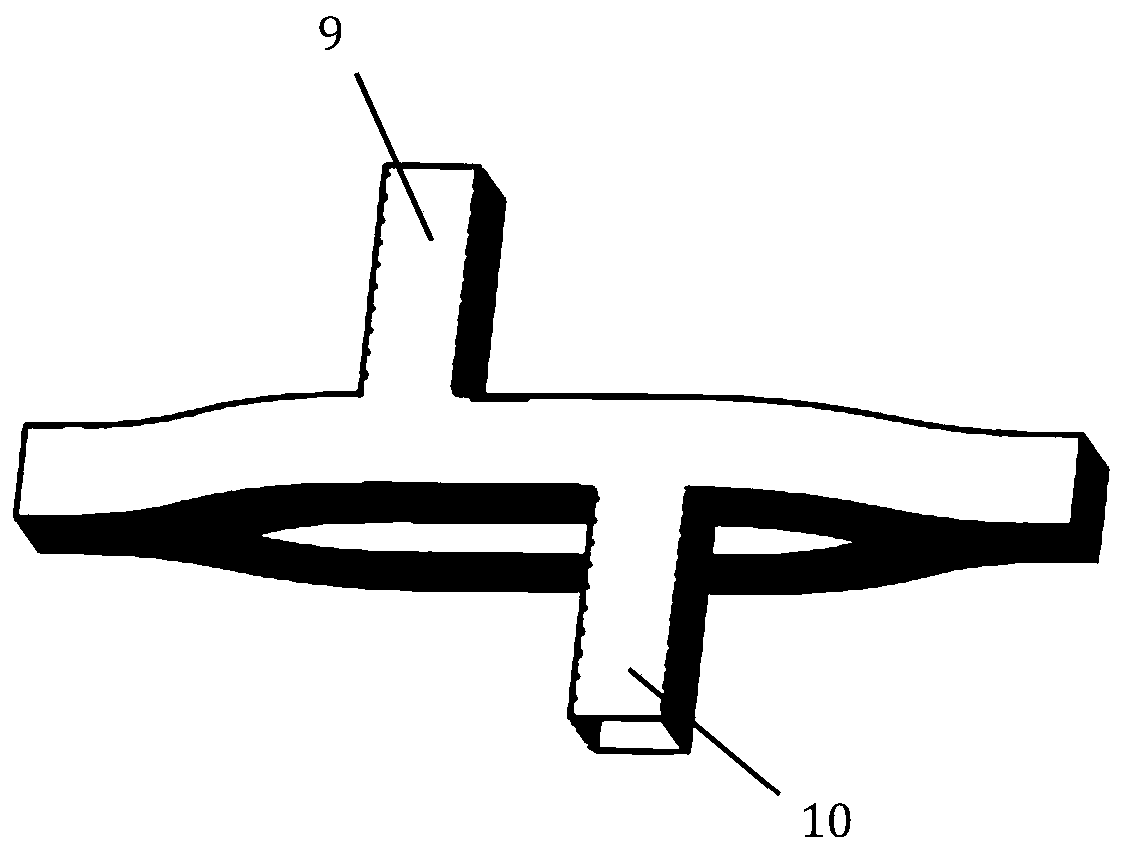
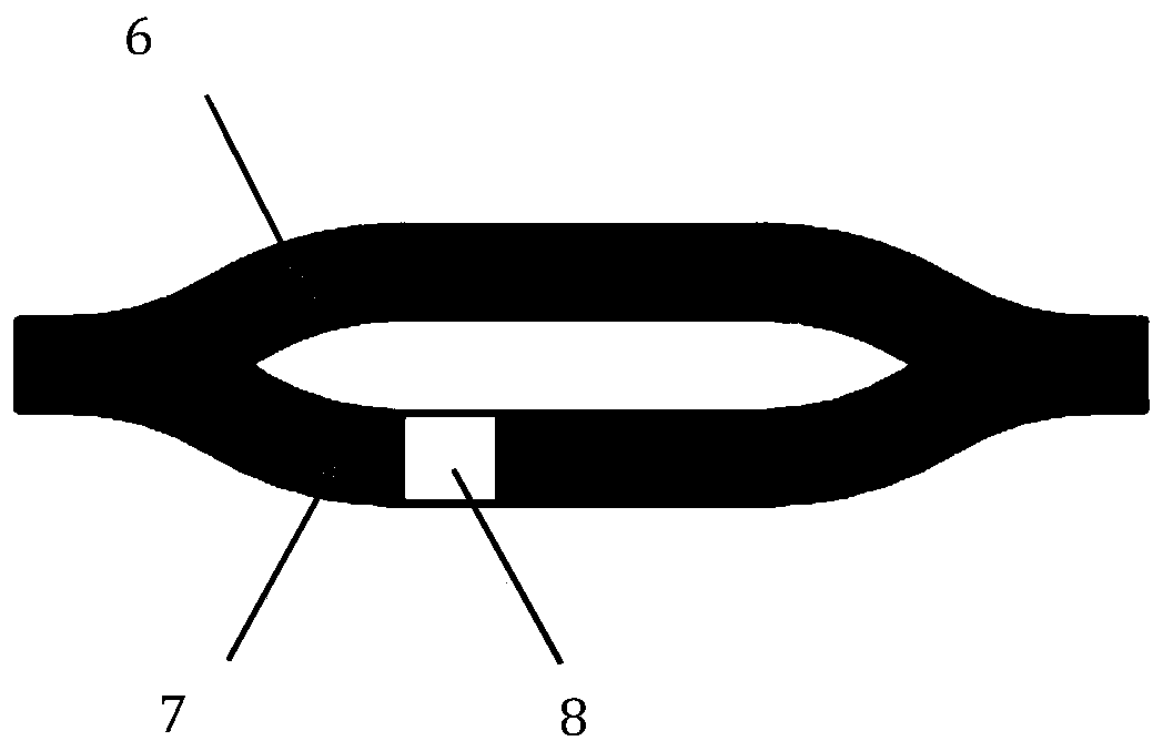
[0029] Such as Figure 1-3 As shown, a high-sensitivity magnetic field sensor utilizing two-photon femtosecond laser direct writing technology 3D printing of the present invention includes incident single-mode optical fiber 2, double Y branch microstructure 3 and outgoing single-mode optical fiber 4; The incident end and the outgoing end of the branch microstructure 3 are respectively connected with one end of the incident single-mode fiber 2 and one end of the exit single-mode fiber 4 . When the described high-sensitivity magnetic field sensor is working, such as figure 1 As shown, the other ends of the incident single-mode fiber 2 and the exit single-mode fiber 4 are respectively connected to a b...


PUM

PropertyMeasurementUnit
thicknessaaaaaaaaaa
lengthaaaaaaaaaa
lengthaaaaaaaaaa

Abstract

The invention discloses a 3D-printed high-sensitivity magnetic field sensor adopting a two-photon femtosecond laser direct writing technology and a manufacturing method thereof. The sensor comprises an incident single-mode optical fiber, a double-Y branch microstructure and an emergent single-mode optical fiber; and the double-Y branch microstructure is directly printed on one end face of the incident single-mode optical fiber and one end face of the emergent single-mode optical fiber, the double-Y branch microstructure comprises a reference arm and a measuring arm, and the measuring arm internally comprises a section of hollow micro-cavity and a micro-flow channel filled with a magnetofluid material. The effective refractive index of a guided mode in the measuring arm is closely related to the refractive index of the magnetofluid, so that propagation light passing through the reference arm and the measuring arm generates a large phase difference after interference at a common end, andan interfered spectrum generates periodic changes due to different effective refractive indexes of the reference arm and the measuring arm. When an external magnetic field changes, valleys of the interfered spectrum drift, and the magnetic field can be measured by measuring the drift. The sensor has the obvious advantages of small size, high sensitivity, corrosion resistance and the like.

Description

technical field [0001] The invention relates to the technical field of optical sensing, in particular to a high-sensitivity magnetic field sensor and a manufacturing method thereof that are 3D printed using two-photon femtosecond laser direct writing technology. Background technique [0002] Magnetic field measurement has important application prospects in power system, aerospace, deep sea exploration and other fields. Currently, various types of optical and electrical based magnetic field sensors for detecting magnetic fields have been proposed, among which the magnetic field sensor based on magnetic fluid (MF) is a potential magnetic field sensor, which uses magnetic fluid as a sensitive substance , the magnetic fluid consists of magnetic nanoparticles (such as Fe 3 o 4 , CoFe 2 o 4 or MnFe 2 o 4 etc.) are suspended and dispersed in certain solvents. Magnetic fluid has magneto-optical properties such as adjustable refractive index, field transmission dependence, Far...

Claims


Application Information

Patent Timeline
Patent Type & Authority Applications(China)
IPC IPC(8): G01R33/032G01R33/00G01D5/353B33Y80/00B33Y10/00B29C64/135
CPCG01R33/032G01D5/35329G01R33/0052B29C64/135B33Y10/00B33Y80/00
Inventor 张登伟梁璀
Owner ZHEJIANG UNIV
Learn More