

A thermoelectric power generation device capable of effectively increasing the end difference temperature
A technology of thermoelectric power generation and thermoelectric power generation sheet, which is applied in the directions of generators/motors, electrical components, metal material coating processes, etc., can solve the problem that the temperature of the low temperature end of the thermoelectric power generation device cannot be effectively reduced, the heat exchange efficiency of the cooling system is limited, and the heat collection The problem of short service life of the material can achieve the effect of high absorption performance, increasing temperature and reducing the temperature of low temperature end.
- Summary
- Abstract
- Description
- Claims
- Application Information
AI Technical Summary
Problems solved by technology
Method used
Image

Examples
Embodiment 1
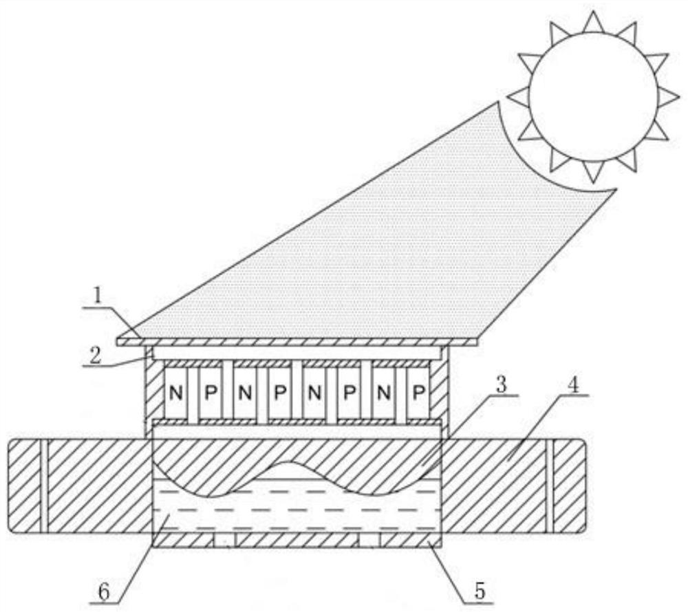
[0031] This embodiment includes a heat collecting device 1, a thermoelectric power generation sheet assembly 2, and a cooling system. The three are arranged sequentially from top to bottom. The high temperature end of the thermoelectric power generation sheet assembly 2 is in fixed contact with the lower surface of the heat collection device 1. The cooling system includes a heat sink. 3. Bracket 4, acrylic plate 5, peristaltic pump and cooling water tank, the lower surface of heat dissipation plate 3 and a plurality of acrylic plates 5 form a heat exchange chamber 6, the heat exchange chamber 6 is fixed on the support 4, and the cooling water tank passes through the peristaltic pump and pipelines It forms a circulation loop with the heat exchange chamber 6, and the upper surface of the cooling plate 3 is in fixed contact with the low-temperature end of the thermoelectric chip assembly 2. The heat collecting device 1 is a red copper plate with a selective absorption film on the u...
Embodiment 2
[0045] The structure of the thermoelectric power generation device of this embodiment is the same as that of Embodiment 1, wherein the preparation steps of the copper plate with selective absorption film are:
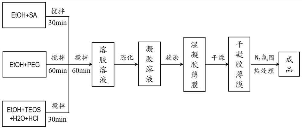
[0046] A. Sol preparation:
[0047] 1) Weigh a certain amount of tetraethyl orthosilicate (TEOS), absolute ethanol (EtOH), deionized water (H 2 (0), hydrochloric acid (HCl) are successively added in the Erlenmeyer flask A, heated in a water bath at 60° C. and magnetically stirred for 30 min;
[0048] 2) Weigh a certain amount of salicylic acid (SA) and a certain amount of absolute ethanol and add them to beaker B in sequence, and continue magnetically stirring at room temperature until the salicylic acid is fully dissolved in absolute ethanol;
[0049] 3) Weigh a certain amount of polyethylene glycol and place it in beaker C, add a certain amount of absolute ethanol, and stir magnetically for 30-60 minutes at room temperature to fully mix;
[0050] 4) Slowly add the s...
Embodiment 3
[0058] The structure of the thermoelectric power generation device of this embodiment is the same as that of Embodiment 1, wherein the preparation steps of the copper plate with a selective absorption film are:
[0059] A. Sol preparation:
[0060] 1) Weigh a certain amount of tetraethyl orthosilicate (TEOS), absolute ethanol (EtOH), deionized water (H 2 (0), hydrochloric acid (HCl) are successively added in the Erlenmeyer flask A, heated in a water bath at 60° C. and magnetically stirred for 30 min;
[0061] 2) Weigh a certain amount of salicylic acid (SA) and a certain amount of absolute ethanol and add them to beaker B in sequence, and continue magnetically stirring at room temperature until the salicylic acid is fully dissolved in absolute ethanol;
[0062] 3) Weigh a certain amount of polyethylene glycol and place it in beaker C, add a certain amount of absolute ethanol, and stir magnetically for 30-60 minutes at room temperature to fully mix;
[0063] 4) Slowly add the...
PUM
| Property | Measurement | Unit |
|---|---|---|
| thermal efficiency | aaaaa | aaaaa |
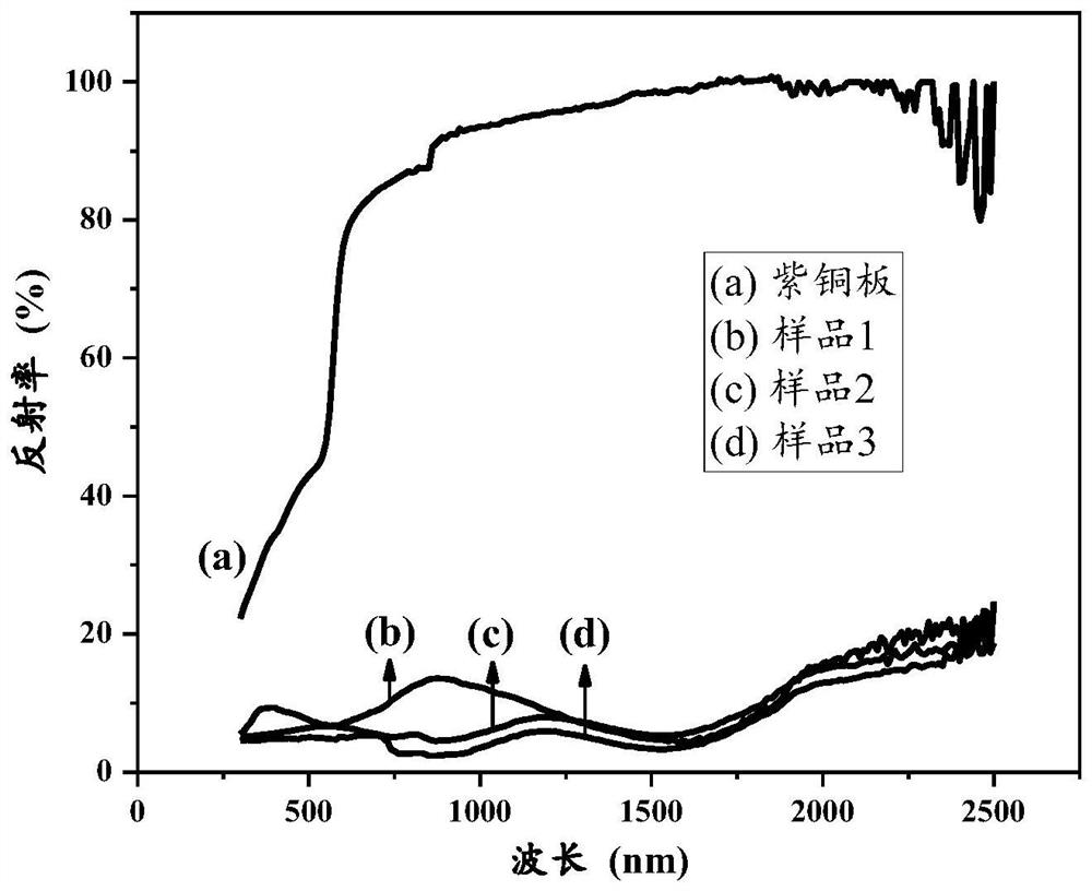
| reflectance | aaaaa | aaaaa |
Abstract
Description
Claims
Application Information