
Valve repair clamp

A technology of valves and fixtures, applied in the field of medical devices, can solve the problems of poor control of the overlapping amount of clamping, high processing and assembly precision requirements, and easy damage of fixture parts, so as to shorten the required time, reduce the overall weight, The effect of increasing the success rate

Pending Publication Date: 2020-07-28
KOKA NANTONG LIFESCIENCES CO LTD
View PDF0 Cites 19 Cited by
  • Summary
  • Abstract
  • Description
  • Claims
  • Application Information

AI Technical Summary

Problems solved by technology

However, this repair method makes the operation more difficult, and it is difficult to control the amount of overlap of the clipping, and it is necessary to open a hole at the apex of the heart. The prior art, such as the patent document with application number 2018800181249, discloses a heart valve sealing device An exemplary implantable prosthetic device having an apposition element and at least one anchor, the apposition element configured to be positioned within a natural heart valve orifice to assist in filling the natural valve regurgitation space and to form a more effective Sealing, the opposition element may have a structure that is impermeable to blood and allows the natural leaflets to close around the opposition element during ventricular systole to prevent backflow of blood from the left or right ventricle into the left atrium or right atrium, respectively, the opposition element may The leaflets connected to the natural valve through anchors will cause additional damage to the patient's body and heart
However, the structure of the above-mentioned technical scheme is complicated, and the precision of processing and assembly is high, and the parts of the fixture are easily damaged during the high-frequency movement of the valve, and the fixture itself is likely to cause greater pressure on the valve.

Method used


Image

  • Valve repair clamp
  • Valve repair clamp
  • Valve repair clamp

Examples


Embodiment 1

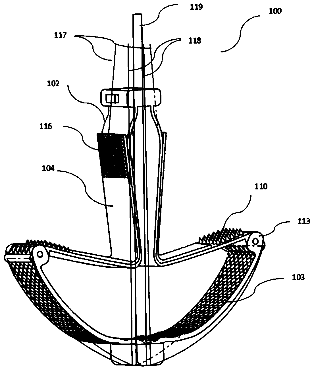
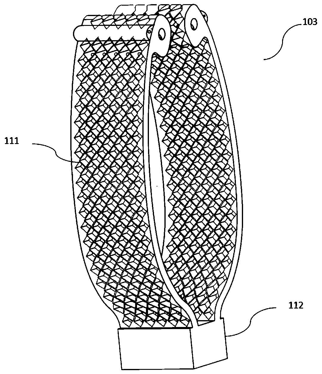
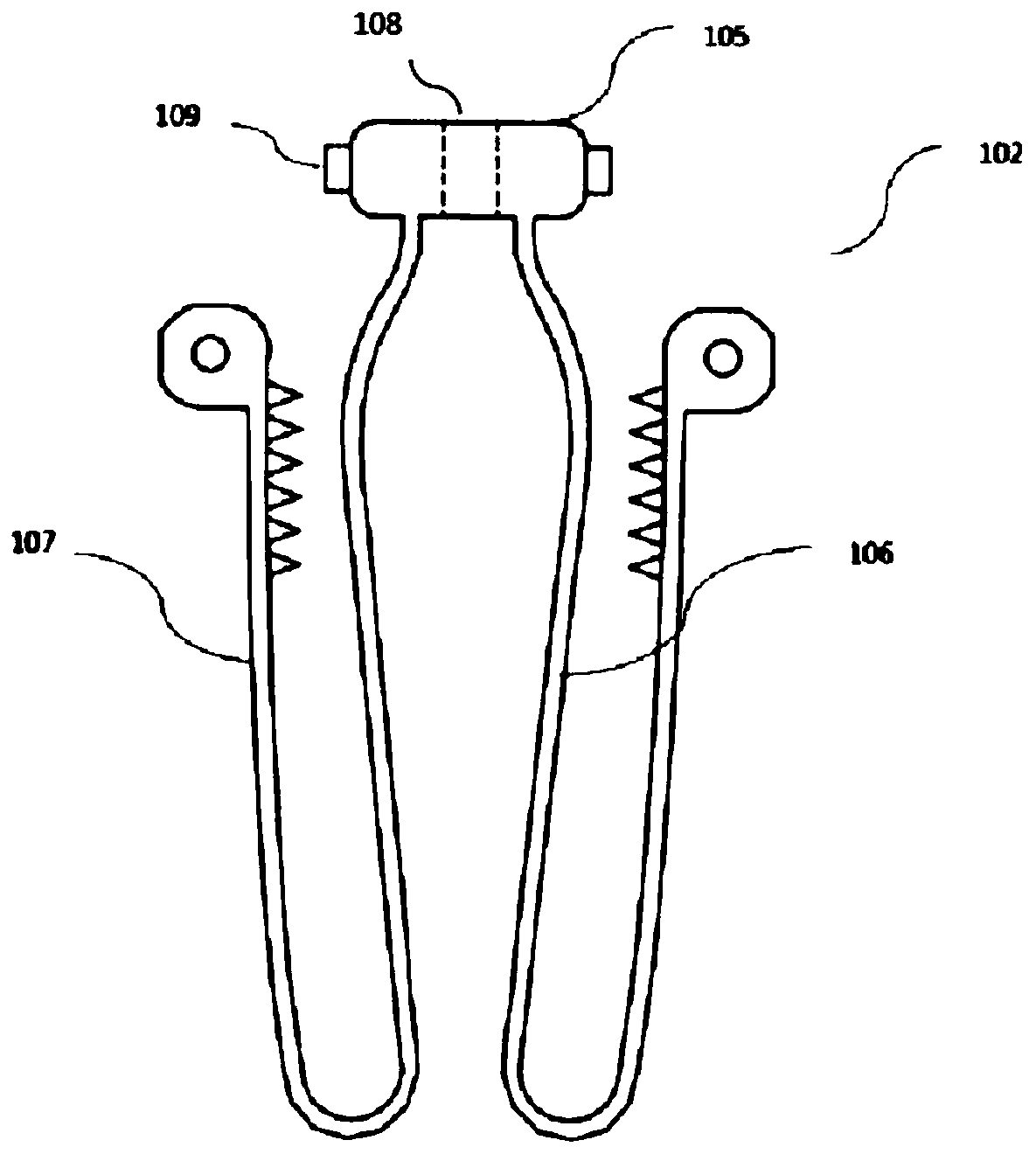
[0036] Such as Figure 1-9 As shown, the valve repair clip 100 of this embodiment is used to implant a damaged valve through a delivery device, and includes an inner clip 102, an outer clip 103, and a splint 104. The inner clip 102 and the outer clip 103 can extend from the folded closed position to When the inner and outer clamps 103 are opened, the splint 104 includes a fixed arm 114 and a movable arm 115. The fixed arm 114 is fixed on the inner clamp 102 and moves with the inner clamp 102; the outer clamp 103 includes a base 112 and an outer clamp on the base 112 Braiding arm 111, outer clip braiding arm 111 forms the clamping surface of V-shaped outer clip 103; The inner clip 102 is W-shaped, including the top seat 105, the overall inverted V-shaped inner clip inner plate 106, the inner clip under the top seat 105. Clamp the outer plate 107, the inner clamp inner plate 106 and the inner clamp outer plate 107 form two V-shaped inner clamp 102 clamping surfaces, the inner cl...

Embodiment 2

[0046] The valve repair jig of this embodiment is different from Embodiment 1 in that:

[0047] In this embodiment, the braiding arm of the outer clip and the outer plate of the inner clip are an integral structure, which is integrally cut and formed by elastic metal, and the connection part is relatively thin, so that it can easily deform. Compared with Embodiment 1, the integral cutting and forming operation is more convenient, and the cumbersome process of using hinge joints is omitted.

[0048] For other structures, refer to Embodiment 1.

Embodiment 3

[0050] The valve repair jig of this embodiment is different from Embodiment 1 in that:

[0051] The fixed arm of the splint in this embodiment is fixed on the inner plate, and its moving arm has the elastic force to clamp the outer plate inward, which can also play the effect of clamping the leaflets. In order to overcome the elastic force that can move outward The radial dimension of the clamp will become larger, so the outer clamp arm is wider and more elastic than the outer clamp arm in Embodiment 1. Compared with Embodiment 1, it is easier to fix the splint fixing arm on the inner plate of the inner clamp.

[0052] For other structures, refer to Embodiment 1.


PUM

PropertyMeasurementUnit
Lengthaaaaaaaaaa

Abstract

The invention relates to the technical field of medical instruments, and particularly relates to a valve repair clamp. The valve repair clamp comprises an inner clamp, an outer clamp and a clamping plate, wherein the inner clamp and the outer clamp can extend from a folding closed position to an inner clamp open state and an outer clamp open state, the clamping plate comprises a fixed arm and a movable arm, and the fixed arm is fixed to the inner clamp and moves along with the inner clamp; the outer clamp comprises a base and an outer clamp braided arm on the base; and the movable arm is further connected with a first control wire to control clamping of the movable arm and an outer plate of the inner clamp. According to the valve repair clamp, the overall weight of the clamp is reduced, the clamp is not prone to damage and loses functionality, damaged valve leaf tissue is successfully repaired through the special structure of the clamp, the physiological function of a valve is restored, the functional life of the valve is prolonged, the success rate of an operation and the convenience of the operation are improved, and damage to a patient is reduced.

Description

technical field [0001] The invention relates to the technical field of medical instruments, in particular to a valve repair clip. Background technique [0002] Regurgitation is a common valvular disorder. Regurgitation is due to the inability of the valve leaflets to close completely, causing blood to flow back into the pumping chamber. Valve ring expansion, valve leaflet prolapse, and valve leaflet movement obstruction are the main causes of regurgitation. Many diseases, such as rheumatic heart disease , Endocarditis causes valvular lesions that impair valvular function. [0003] At present, there are mainly valve replacement techniques and valve repair techniques for valve leaflet treatment. Leaflet replacement technology uses artificial valves to replace existing diseased or abnormal heart valves. This kind of replacement operation often requires open chest operation, which causes great damage to the patient's body. Valve repair is a procedure in which a clip is deliv...

Claims


Application Information

Patent Timeline
IPC IPC(8): A61F2/24
CPCA61F2/2442A61F2/2466A61F2/246A61F2220/0016
Inventor 陈大凯
Owner KOKA NANTONG LIFESCIENCES CO LTD
Learn More