

A high-speed laser pulse sampling detection circuit, system and method
A technology of laser pulse and detection circuit, which is applied in the direction of radio wave measurement system, measurement device, electromagnetic wave re-radiation, etc., can solve the problem of accurate sampling and detection without high-speed laser pulse
- Summary
- Abstract
- Description
- Claims
- Application Information
AI Technical Summary
Problems solved by technology
Method used
Image

Examples
Embodiment 1
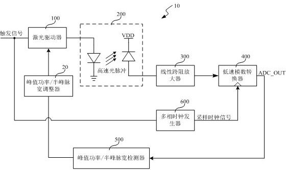
[0051] Such as figure 1 As shown, the present embodiment provides a high-speed laser pulse sampling detection circuit, and the sampling detection circuit 10 includes:
[0052] A laser driver 100, configured to generate a laser pulse signal driven by a trigger signal;
[0053] A photoelectric converter 200, connected to the output end of the laser driver 100, for converting the laser pulse signal into a current pulse signal;
[0054] A linear transimpedance amplifier 300, connected to the output end of the photoelectric converter 200, for amplifying the current pulse signal and converting it into a voltage pulse signal;
[0055] A low-speed analog-to-digital converter 400, connected to the output end of the linear transimpedance amplifier 300, for sampling the voltage pulse signal driven by a sampling clock signal and performing analog-to-digital conversion to it;
[0056] The peak power / half-peak pulse width detector 500 is connected to the output end of the low-speed analog...
Embodiment 2
[0091] Such as figure 1 As shown, this embodiment provides a laser radar / 3D sensor system, the laser radar / 3D sensor system includes: a transmitter and a receiver, wherein the transmitter includes: the high-speed laser as described in Embodiment 1 The pulse sampling and detection circuit 10 is used for sampling and detecting the laser pulse signal to obtain its peak power and half-peak pulse width.
[0092] As an example, such as figure 1 As shown, the transmitting end also includes: a peak power / half-peak pulse width regulator 20, connected to the output end of the peak power / half-peak pulse width detector 500 and the control end of the laser driver 100, for An adjustment control signal is generated according to the detected peak power and half-peak pulse width to control the peak power and half-peak pulse width of the laser pulse signal output by the laser driver 100 . Specifically, under the driving of the trigger signal, the laser driver 100 adjusts the peak power and th...
PUM
 Abstract
Description
Claims
Application Information