SiC power tube driving circuit with active crosstalk suppression function and control method

A technology for driving circuits and power tubes, applied in output power conversion devices, electrical components, high-efficiency power electronic conversion, etc., can solve the risk of increasing the reverse breakdown of the switch, the miscellaneous inductance cannot be completely eliminated, and reduce the forward peak of the switch. value and other issues, to achieve good suppression effect, speed up switch turn-off speed, and reduce positive and negative voltage spikes.

Active Publication Date: 2020-07-28
HUNAN UNIV
View PDF7 Cites 8 Cited by
  • Summary
  • Abstract
  • Description
  • Claims
  • Application Information

AI Technical Summary

Problems solved by technology

[0005] First of all, reducing the parasitic inductance is the simplest method, but since the stray inductance cannot be completely eliminated in the actual circuit, this method has limitations
Secondly, increasing the resistance of the driving resistor and connecting a capacitor in parallel between the gate and source of the SiC switch can also achieve the effect, but this will reduce the switching performance, so the parameters need to be reasonably balanced when designing the driving circuit
In addition, the use of negative pressure driving can effectively reduce the positive peak value in the switch, reducing the probability of the switch being turned on by mistake, but this also increases the risk of reverse breakdown of the switch

Method used


Image

  • SiC power tube driving circuit with active crosstalk suppression function and control method
  • SiC power tube driving circuit with active crosstalk suppression function and control method
  • SiC power tube driving circuit with active crosstalk suppression function and control method

Examples


Embodiment Construction

[0055] The present invention will be further described below with reference to the drawings and specific embodiments of the specification.

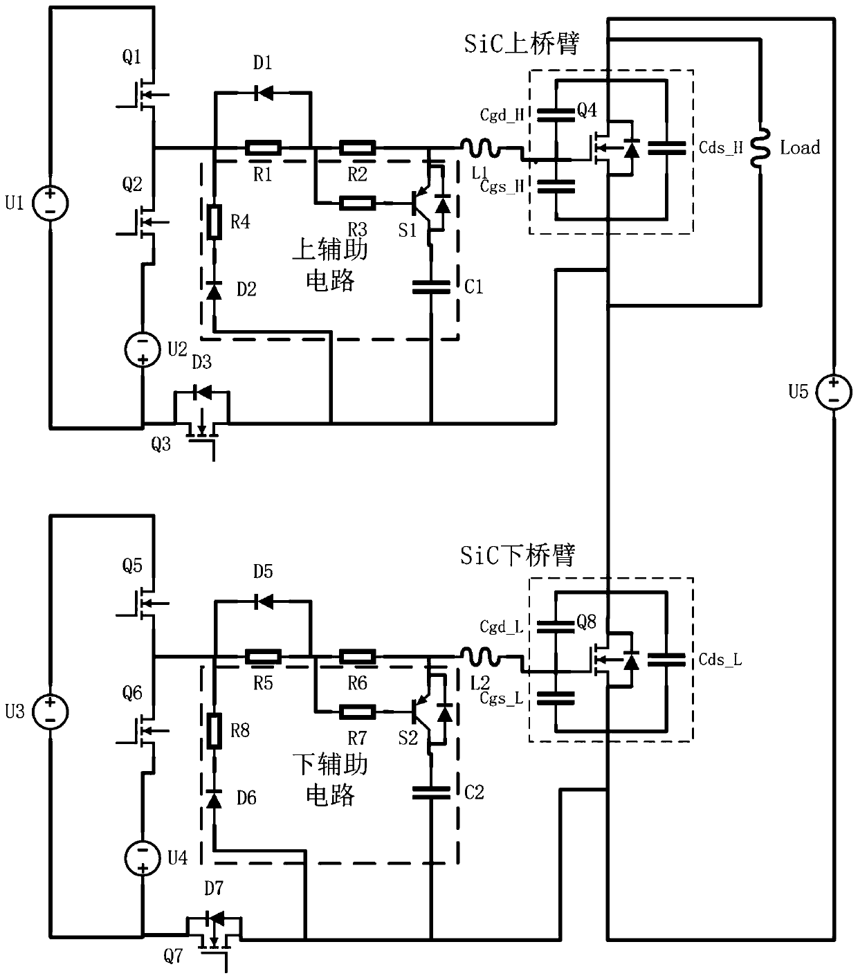
[0056] Such as figure 1 As shown, this embodiment discloses a SiC power tube driving circuit with active crosstalk suppression function, including a basic driving circuit and an auxiliary circuit. The basic driving circuit includes an amplifier circuit, a resistor R1, a resistor R2, and a diode D1. One end of the resistor R1 Connected to the output positive end of the amplifying circuit, the other end is connected to one end of the resistor R2, the other end of the resistor R2 is connected to the gate of the SiC power tube, the anode of the diode D1 is connected to the other end of the resistor R1, and the cathode is connected to the One end of the resistor R1 is connected; the auxiliary circuit includes a resistor R3, a resistor R4, a capacitor C1, a transistor S1, a diode D2, and a MOS transistor Q3. The emitter of the transistor S1 is conn...


PUM


Abstract

The invention discloses a SiC power tube driving circuit with an active crosstalk suppression function. The driving circuit comprises a basic driving circuit and an auxiliary circuit, wherein the basic driving circuit comprises an amplifying circuit, R1, R2 and D1, one end of the R1 is connected with the amplifying circuit, the other end of R1 is connected with one end of the R2, the other end ofthe R2 is connected with a grid electrode of a power tube, a positive electrode of the D1 is connected with the other end of the R1, a negative electrode of the D1 is connected with one end of the R1,the auxiliary circuit comprises R3, R4, C1, S1, D2 and Q3, an emitter of the S1 is connected with the other end of the R2, one end of the R3 is connected with the other end of the R1, the other end of the R3 is connected with a base of the S1, two ends of the C1 are respectively connected with a collector of the S1 and a source of the power tube, an anode of the D2 is connected with a source of the Q3, the cathode is connected with one end of the R4, the other end of the R4 is connected with one end of the R1, a drain of the Q3 is connected with the amplifying circuit, and the source is connected with a source of the power tube. The driving circuit has advantages of simple structure, simple overall structure, low cost, easy control, crosstalk suppression and the like.

Description

Technical field [0001] The invention relates to the technical field of power electronics, in particular to a SiC power tube drive circuit and a control method with active crosstalk suppression function. Background technique [0002] In power electronic systems, the performance of semiconductor power devices directly affects the power conversion efficiency of the entire system. In recent years, the third bandwidth bandgap semiconductor power devices represented by SiC and GaN have gradually replaced traditional semiconductor devices made of Si with their excellent switching performance. [0003] Compared with GaN, SiC semiconductor power devices have higher withstand voltage and higher power. They are widely used in high-power fields such as high-speed rail aerospace, photovoltaic power generation and new energy vehicles, and have good application prospects. The use of SiC semiconductor power switches is beneficial to greatly increase the switching frequency, reduce switching losse...

Claims


Application Information

Patent Timeline
Patent Type & Authority Applications(China)
IPC IPC(8): H02M1/08H02M1/088H02M1/32
CPCH02M1/08H02M1/088H02M1/32H02M1/0038Y02B70/10
Inventor 刘侃肖捷丁荣军栾皓喆周世超高莉
Owner HUNAN UNIV
Why Eureka
Try Eureka