
Off-line identification method for moment of inertia of permanent magnet synchronous motor

A permanent magnet synchronous motor and moment of inertia technology, which is applied in the direction of controlling generators, motor generators, electromechanical brakes, etc., can solve the problems of mechanical acceleration signal errors, inability to accurately identify moments of inertia, etc., and achieve small calculations and algorithms The effect of simplicity and high recognition accuracy

Inactive Publication Date: 2020-07-28
SOUTH CHINA UNIV OF TECH
View PDF3 Cites 8 Cited by
  • Summary
  • Abstract
  • Description
  • Claims
  • Application Information

AI Technical Summary

Problems solved by technology

In the servo system, the feedback value of the speed is calculated according to the position pulse increment of the encoder in a single cycle. The calculation of this step itself is a differential operation. During the actual operation of the motor, the vibration of the machine and the adjustment of the control parameters of the servo system are different. Factors such as reasonableness and external load disturbance will cause the jitter of the encoder feedback position. The jitter of the position is amplified by differential operation and superimposed on the feedback speed signal. If the feedback speed is used for differential operation, the obtained mechanical acceleration signal will be There will be a large error, and the moment of inertia cannot be accurately identified

Method used


Image

  • Off-line identification method for moment of inertia of permanent magnet synchronous motor
  • Off-line identification method for moment of inertia of permanent magnet synchronous motor
  • Off-line identification method for moment of inertia of permanent magnet synchronous motor

Examples


Embodiment

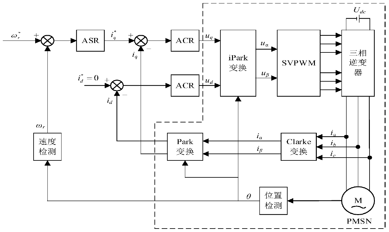
[0024] Such as figure 1 The control structure diagram of the permanent magnet synchronous motor inertia identification system is shown. The system block diagram is composed of the inner loop of the current loop and the outer loop of the speed loop. The encoder collects the electrical angle signal as the feedback signal of the speed loop, and the sampling module samples the three-phase current signal of the motor. After the coordinate transformation, it is used as the feedback signal of the current loop. The current loop output signal passes through the SVPWM module to generate the voltage signal required for the motor to run. The present invention is all completed in the speed loop of vector control, adopts the planned speed command for the input of the speed loop to make the motor operation carry out two identifications, obtains the q-axis current and the rotor position of the same sampling period from the motor, and compares the q-axis current and the rotor position Input t...


PUM


Abstract

The invention discloses an off-line identification method for moment of inertia of a permanent magnet synchronous motor. The method comprises the steps of planning a speed instruction given by a speedring to enable the motor to operate for twice identification; sampling a feedback current value and a rotor position from a servo system at the same time when the motor runs in a controllable stroke;and inputting the current feedback signal and the rotor position signal into a designed model to calculate the moment of inertia so as to obtain a relatively accurate inertia identification result. According to the method, the problems that the influence caused by viscous friction cannot be ignored by a traditional off-line identification method, errors are introduced by differential operation inthe calculation process, and the application occasions are limited are solved. According to the method, the accuracy of an identification result can be effectively improved, and the total inertia ofthe system can be rapidly and accurately identified in an occasion with a load.

Description

technical field [0001] The invention relates to the field of inertia identification of synchronous motors, in particular to an off-line identification method for rotational inertia of permanent magnet synchronous motors. Background technique [0002] With the application of permanent magnet servo system more widely, the research of high-performance servo system characterized by high precision and high speed has received extensive attention. In the field of servo system application, the system is required to have a good response to load changes and speed changes. Dynamic response, and the change of the moment of inertia and load torque will seriously affect the performance of the system. In order to achieve good high-precision control dynamic and static characteristics of the servo system, it is necessary to accurately identify the inertia of the system and adjust the control accordingly device parameters. Offline identification is to measure and collect the actual speed and...

Claims


Application Information

Patent Timeline
IPC IPC(8): H02P21/14
CPCH02P21/143
Inventor 王孝洪任连新郑立楷黄淇松周鑫东王雨
Owner SOUTH CHINA UNIV OF TECH
Learn More