Plasma jet generation device and system
A technology of plasma and generating device, applied in the field of plasma jet, can solve the problems of poor stability, easy discharge termination, affecting jet quality, etc., and achieve the effects of increasing content, increasing energy, and increasing effect
- Summary
- Abstract
- Description
- Claims
- Application Information
AI Technical Summary
Problems solved by technology
Method used
Image
Examples
Embodiment 1
[0029] The first embodiment of the present invention proposes a plasma jet generating device, including: a tube body and electrodes;
[0030] Wherein, the electrodes surround the outer surface of the tube body;
[0031] The pipe body includes a gas input end for receiving the working gas and a jet end for emitting the plasma jet;
[0032] After the working gas is fed into the gas input end, the electrodes are used to apply a voltage to the working gas in the tube until the working gas breaks down to form a plasma jet.
[0033] Specifically, in this embodiment, the electrodes are spaced around the tube body to form a plurality of intervals in the tube body for sufficient collision and excitation of gas particles, which can increase the content of active groups in the jet, and can effectively avoid impurity elements Mixed into the jet to increase the energy of the jet, and improve the effect of hydrophobic and other modification treatments when performing surface modification o...
Embodiment 2
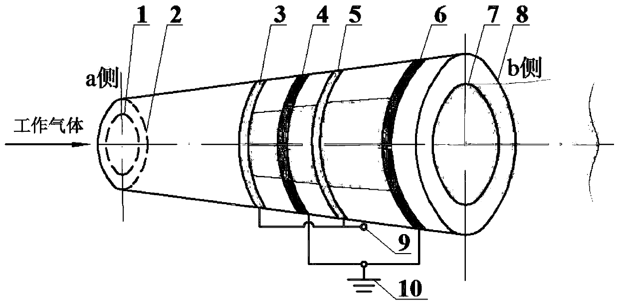
[0051] This embodiment proposes an implementation case of a plasma jet generating device. In this embodiment, it includes: a funnel-shaped plasma jet tube and an electrode, wherein the tube body is a quartz glass tube, and the tube body includes a gas input end and a jet end of the end, such as figure 1 As shown, the first inner diameter 1 of the gas input end is 4mm and the second inner diameter 2 of the gas input end is 6mm, the first inner diameter 7 of the jet end is 8mm and the second inner diameter 8 of the jet end is 10mm, the length of the glass tube is 84mm, and the wall thickness is 2mm.
[0052] In this example, if figure 1 As shown, the electrodes include four ring electrodes, and of course other even numbers of electrodes are not limited here. The four ring electrodes are attached to the outside of the funnel-shaped jet tube, and the electrodes have a width of 3 mm and a thickness of 2 mm. Made of copper sheet. The four ring-shaped electrodes are composed of two...
Embodiment 3
[0065] This embodiment proposes a plasma jet generation system, including a gas flow controller, an adjustable power supply and the aforementioned plasma jet generation device;
[0066] The output end of the gas flow controller is connected to the gas input end of the plasma jet generator, and the gas flow controller communicates with the inner hole of the pipe body;
[0067] The adjustable power supply is connected to the electrodes of the plasma jet generating device;
[0068] The gas flow controller is used to adjust the flow of working gas passing into the pipe body;
[0069] The adjustable power supply is used to change the parameters of the voltage applied to the electrodes to break down the working gas.
[0070] Optionally, the voltage parameters include: voltage peak value and frequency.
[0071] Specifically, the workflow of the system of the present invention is as follows:
[0072] 1. Pass in the working gas, so that the working gas enters the funnel-shaped quart...
PUM
| Property | Measurement | Unit |
|---|---|---|
| Thickness | aaaaa | aaaaa |
Abstract
Description
Claims
Application Information
 - R&D
- Intellectual Property
- Life Sciences
- Materials
- Tech Scout
- Unparalleled Data Quality
- Higher Quality Content
- 60% Fewer Hallucinations
Browse by: Latest US Patents, China's latest patents, Technical Efficacy Thesaurus, Application Domain, Technology Topic, Popular Technical Reports.
© 2025 PatSnap. All rights reserved.Legal|Privacy policy|Modern Slavery Act Transparency Statement|Sitemap|About US| Contact US: help@patsnap.com

